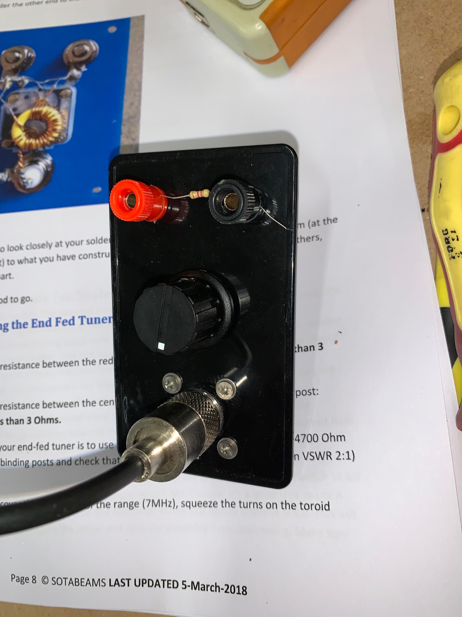
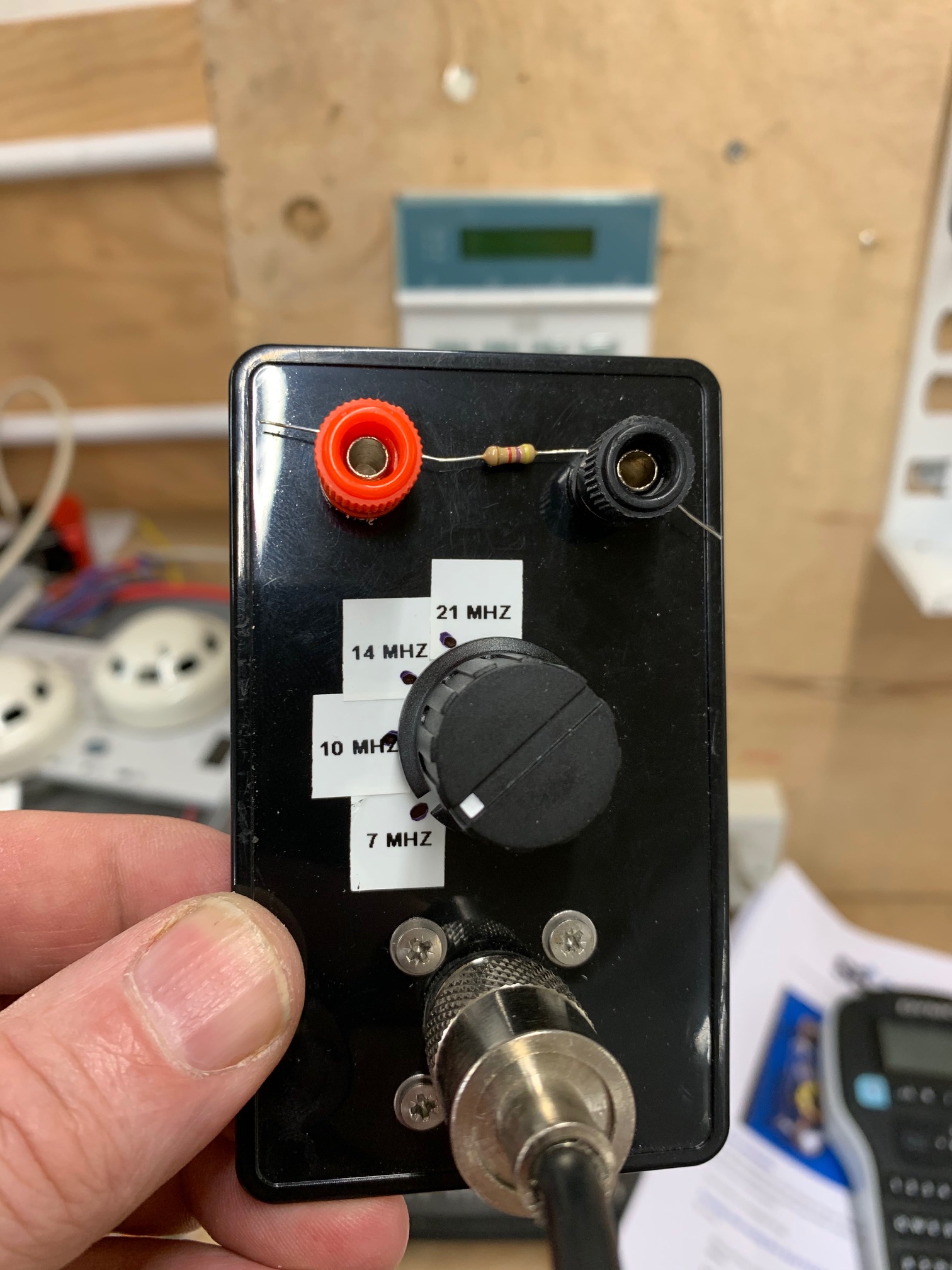
Hi all can anyone help please. I mainly operate SOTA and like to build my own antennas. Last week I saw the sotabeams mountain tuner. It looks like it is no longer for sale anywhere so I decided to bake my own.
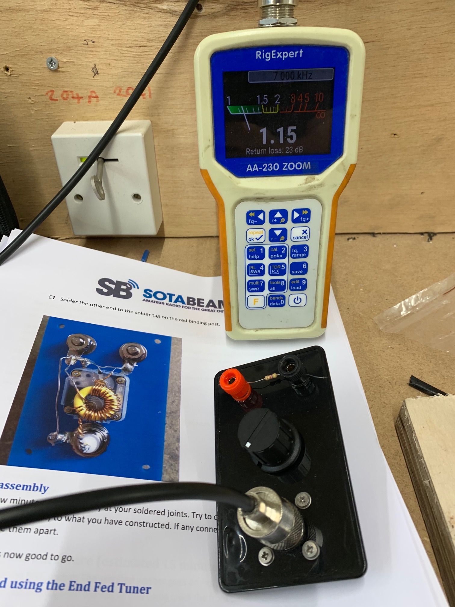
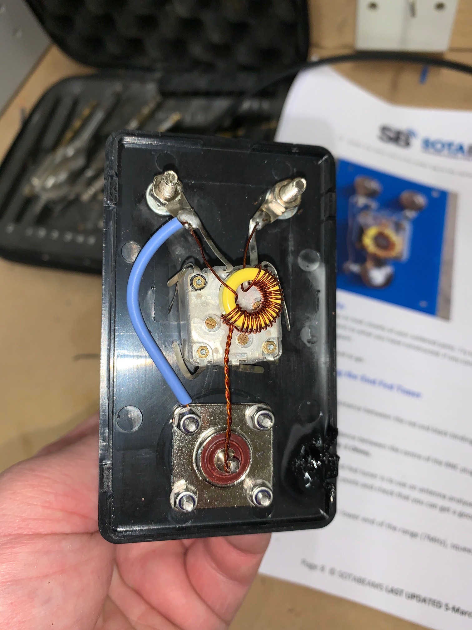
The variable capacitor is 0-270 pf and the toroid is a T50-6. I followed diagrams that I found online. Testing I used a 4700 ohm resistor and I was happy with the results.
Today I started adding the various lengths of wire. I am using the thin yellow wire that you can purchase from sotabeams sorry forgot what it’s called.
The lengths are as follows:
17M is 7.9m
20M is 10.1m ( an additional 2.2m)
30M is 14.2m ( an additional 4.1m)
40M is 20.3m ( an additional 6.1m)
This is what found online.
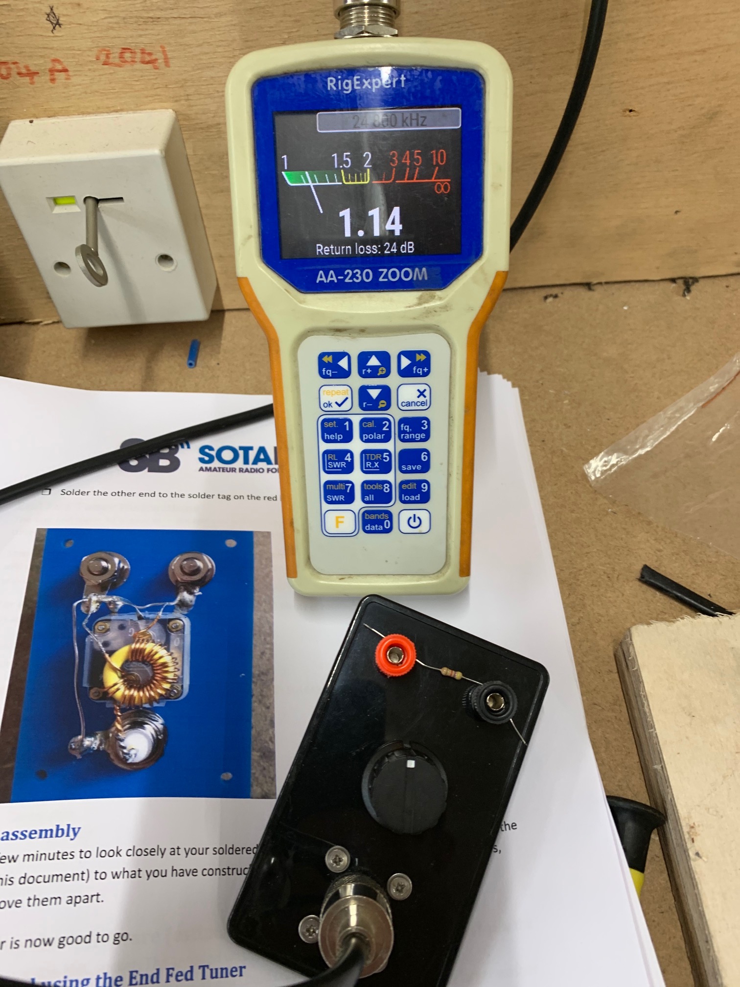
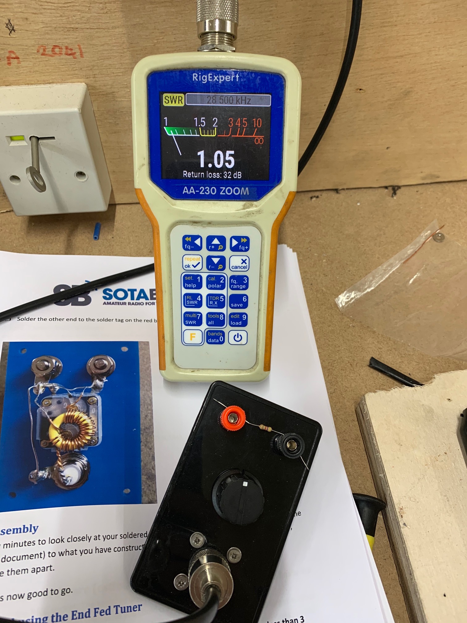
I used the first length and managed to get an swr at 1.31 which I thought looks ok. The problem started on the next length as I could not get any swr lower than 22. I then swapped the connection lead from red to the black and black to the red so basically the counterpoise and antenna around. This then let me have 1.04 swr.
If you haven’t already you might want to read the web pages by Steve Yates, AA5TB on the subject of “The End Fed Half Wave Antenna”
The main difference between your tuner and his design appears to be that you have connected the coax ground to the counterpoise where he keeps them separate. I’ve built several using his design and they all work well.
There is a striking resemblance between the AA5TB design and the W3EDP antenna which dates from the 1930s. The difference is that the W3EDP antenna is a single length of wire but the counterpoise varies by band. I use a counterpoise wire on a spool, marked with tape at the different lengths.
Paul,
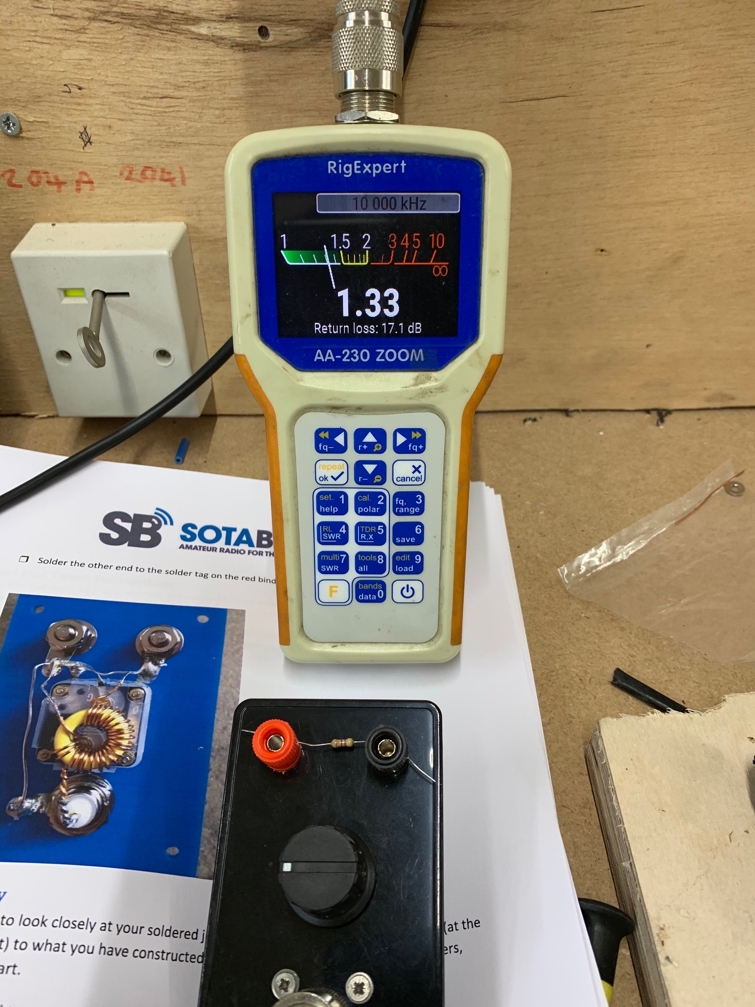
Why in the world don’t you look where the resonance frequency is on the graphic display?
The SWR alone cannot say that. If the resonance frequency is too low the antenna is too long and vice versa.
Hi There but doesnt that change with the rotation of the knob for the capacitor? or doesnt that change it? I thought it would but must admit didnt look.
EFHW length adjustment, start with highest frequency band
Select SWR chart (Key 4), then desired resonance frequency (Key 3)
Select frequency range (Key 3), start with abt. 3 kHz and gradually decrease it
Connect the EFHW and start measurement (Key ok)
Shorten/lengthen the radiator until it resonates at the desired frequency
Look for the best SWR and adjust the mark for the variable capacitor
The radiator length for this band is sacrosanct now, never touch it again
Add the extension for the next lower frequency band and repeat steps 1)-6) for the frequency of the new band only.
The geometry of the antenna arrangement (e.g. apex height, radiator strength/inv-V/inv-L) has an impact on the resonance frequencies. It is therefore recommended to make the length adjustment with the intended “standard” antenna geometry.