I started using my Fuchskreis on 80m and found that the best SWR I could get was 1.4. Instead of taking the whole thing apart and adding more windings, I followed Steve Weber’s advice and just made the wire 2m longer. Best SWR now 1.2 and no discernable effect on efficiency.
73
Matt
Matt,
The Fuchskreis has only one variable capacitor. This is also true of many other simple tuners. This is part of the reason that the SWR is not 1.0:1.
With two variable capacitors, one for coupling, and the other for tuning, it may be possible to adjust the SWR to 1.0:1. The coupling variable capacitor is usually connected in series with the primary or input of the transformer.
My tuner will give SWR of 1.0:1 in most cases, within the range of frequencies, and with reasonable wires.
73
George
KX0R
1 Like
Yes, I was intrigued when I read that you had a variable capacitor for the coupling as well. That is something I would definitely like to try, thanks for the tip.
73
Matt
Matt,
Try connecting the second variable capacitor in series with the primary winding - use a separate primary winding, not a single tapped winding. Most of the Fuchs circuits already have taps in this winding. These taps provide considerable control of coupling.
The series capacitor should be in placed the low impedance or ground side of the primary.
There are many variations on these circuits. The Fuchs is unbalanced, for feeding the end-fed antennas. Other designs are balanced, for use with open wire transmission line.
My tuner is not very different from the Fuchskreis circuits found on many Internet sites. I don’t have any rotary switches - I do use tiny switches to modify the circuits for high and low frequencies.
The polyvaricon capacitors use a thin polyethylene film, and they probably should not be used at power levels much over 10W. Tuning should be done at lower power to avoid damaging the components of the tuner. Always have the antenna connected.
73
George
KX0R
2 Likes
Hi George
I find you description interesting me.
Can you put your tuner shematic, I had a BLT tuner + (not working well with EFHW)
and I’ll try to adapte it.
73 Eric F5JKK
1 Like
Hi George
I wanted to know what you think of the MFJ-9201
tuner. It seems ruffly similar to what you made.?
Thanks Richard wa6kyr
Richard,
While the MFJ-9201 looks a bit similar to my tuners, I don’t think it uses the same circuit.
I looked at the manual, and there’s no schematic shown, nor could I find it on the Internet with a quick search. Based on the instructions in the manual, I think the MFJ-9201 is a T-network. Hopefully someone else here can confirm that.
What’s good about T-networks is that they match a wide range of impedances, and they also give very accurate matches, if used carefully. I would guess that at least half the tuners sold are T-matches. They’re popular, because they give a good mix of performance versus cost. With just three variables, you can match most normal antennas, if they have an unbalanced feed - coax or single wire.
The T-match has a range of matches possible for many loads, but not all those matches are ideal. The instructions for the MFJ-9201 say that the minimum inductance that will give a good match should be used. They also mention possibility of damage with using too much inductance, and a few other limits.
A T-match can give a match that tunes OK and seems good, but there might be more loss in the tuner than what would be possible with a different adjustment. There’s no easy way to tell without additonal equipment. Use the minimum inductance, etc.
For portable operating at 10W or less, the MFJ-9201 looks OK - as long as you follow the instructions in the manual.
This would not be my choice for feeding an end-fed half wave, but it probably will work. Since I’ve never used this tuner, I can’t add much.
There are ways to check the efficiency of a tuner, but fairly technical work is needed to get reliable results. One thing you can do, if you want to test a tuner for various loads, is to use it with resistors at very low power. Use no more power than the ratings of your resistors.
With many tuners you can get matches that are extremely critical with some loads - I call these sharp matches. Sometimes they’re OK - efficiency is still good - but sometimes a really sharp match indicates that the tuner is having difficultly matching the impedance, and it’s operating outside of its normal range.
Any antenna tuner has its good and bad points. A lot of operators like T-networks, because they get to know them and learn their settings.
You might try to find technical reviews for any tuner you’re thinking of using. QST and other experts do technical reviews of popular tuners, especially the larger tuners.
73
George
KX0R
Eric,
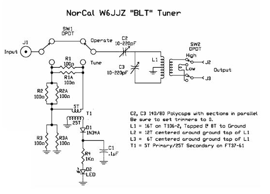
I also have used the BLT with an end-fed half wave EFHW antenna, but it is not ideal. The BLT really is not designed for feeding very high impedance loads.
The problem is that the “HIGH Z” secondary winding, the winding with more turns, still has fewer turns than L1, the main winding.
If you increase the turns of the High Z winding, you may be able to have better performance when using the EFHW. One way to do this is to test the BLT with a load resistor of about 3000 ohms connected.
You also should connect one side of the output to the ground side of the tuner, so that the Balanced Line Tuner (BLT) is no longer balanced.
With these changes, the tuner will no longer function correctly for balanced lines.
You also could change the circuit in various other ways so it would be more ideal for matching the EFHW. Using a larger tuned secondary with a smaller series-tuned primary should help. All of the same parts can be used.
Very soon I’ll post my circuit that I use for SOTA activations.
73
George
KX0R
2 Likes