A loss of 1.5db has no noticeable effect on the efficiency of the antenna. Most qrp antenna tuners suffer similar losses, especially at random long wires.
It should be indifferent in most cases, whether you heard with S5 or S4 3/4.
The decisive advantage for me, especially for Sota, is that I’m qrv without tuning and without changing over on several bands with a feeding point near by the ground.
73 Chris
I just made a test with a HAM about 5 km from my home.
On 40 m the endfed with the 43 material transformer was 1 S-unit less at the receiving station than with the material 61 transformer! On 20m there was no difference in signal strengh although the power measurement results yesterday showed a higher loss on 20 m.
Endfed with 61 material transformer showed the same S-meter reading compared to my linked dipol.
The performance of my transformer construction is ok from 7 MHz to 14 MHz. Currently I only have FT 114-61 available but for 10 W it should be ok. I am using 3:27 turns and 330 pf…
My endfed is a trap-version for 7/10/14 MHz, halfwave length on each band, no harmonic operation.
Results for me: for the moment I will carry my 61 material modified endfed along for my upcoming activations.
Tanks for the links, there is a lot to read and still a lot to learn about.
And thanks for all the replies
73
Peter
The QRP EFHW xfmr that Owen Duffy recommends is wound on a round cable core (type 43), not a toroid. A crucial parameter for power handling is a parameter related to cross sectional area and path length and this is superior for the cable core versus the toroid. This is the core he used in his recommended xfmr. I suspect it might be challenging winding many turns on it.
73 Barry N1EU
yes, thanks for you comments. EFHW is very good antenna for SOTA, I use it myself also.
What I wanted to know is that has some one measured these transformers and now I can see they have. Thanks for their efforts.
quote “Just wondering if anyone else has measured these famous efhw transformers with diffirent core materials? Oh yes, I know it is only one dB, but thats not the point here.”
73 good luck
Marko OH9XX OH3XR
thanks for the link Barry, will check it
73 Marko OH9XX OH3XR
Peter,
Your conclusion regarding the efficiency of the ferrite mixes 43 and 61 seems to me a bit daring and too generalized (not taking into account the frequency range of operation). The main reason is because not both of the compared Ununs have an optimal design which can falsify the results.
Unun FT-140-61 2t primary
- Core efficiency (along Owen Duffy):
98% @ 7.1 MHz
98% @ 10.1 MHz
96% @ 14.2 MHz
78% @ 28.5 MHz
-> optimal design
-> efficiency drops below 90% at 21 MHz
-> total variation of core efficiency approx. 20%
Unun FT-140-43 2t primary
- Core efficiency (along Owen Duffy):
66% @ 7.1 MHz
67% @ 10.1 MHz
70% @ 14.2 MHz
72% @ 28.5 MHz
-> inefficient design, could be improved by 3t primary (below)
-> total variation of core efficiency approx. 6%
Unun FT-140-43 3t primary (and 21t secondary)
- Core efficiency (along Owen Duffy):
85% @ 7.1 MHz
85% @ 10.1 MHz
86% @ 14.2 MHz
88% @ 28.5 MHz
-> good design
-> total variation of core efficiency approx. 3%
It would be interesting to see if/how the core efficiency (along Owen Duffy) plays in your comparision using a rewound FT-140-43 3t primary and 21t secondary?
Note: The value of the compensation capacitor may need to be adjusted.
Hi Heinz,
My application is only from 7 to 14 MHz, so within this frequency region the FT114-61 transformer efficiency seems to be similar to:
I will try the FT 140-43 with 3 turns primary
73
Peter
Here are efficiency figures for 14MHz per Owen Duffy calculation method for type 43 ferrite and 3T primary. First figure is for single core and second figure is for stacked dual cores:
FT82-43 73% 87%
FT114-43 75% 88%
FT140-43 86% 93%
73 Barry N1EU
That is what I measured yesterday. At 14 MHz FT 140-43 (2 T primary) single core loss 1.75 W, that results in an efficiency of about 83 % or am I wrong?
Peter
Peter, Owen Duffy calculates only 68% efficiency with 2T primary. It climbs to 86% with 3T.
Barry
Ferrite materials can vary considerably depending on the manufacturer and even the batch. Tolerance for AL is typically +/- 20% so it’s possible that this is just a particularly efficient core. The core could be anywhere from ~60% to ~74% efficient with 2 primary turns and still be within tolerance.
Peter, if you’d like a better idea of what the AL of that core is you can do a quick test by putting a bunch of turns (Fair Rite uses 5) through the toroid, measure the inductance in uH, then do a bit of algebra and work out the final value: uH=(AL*Turns^2)/1000.
Cheers,
John VA7JBE
As a not so well qualified layman, it is not so clear to me what is being implied here. Are we talking about insertion loss or blocking impedance, or neither? Doesn’t the importance of one over the other depend on what kind of antenna you are building!
Cheers Matt
FWIW I often find this link useful:
I believe the efficiency numbers are losses incurred in the transformer material. Another consideration is SWR losses introduced by too low inductive reactance of the primary winding (which is effectively in parallel with the transformed impedance of the antenna, which should be 50 ohms by design). A primary inductive reactance of 100 ohms results in an SWR of 1.5:1 if the antenna is optimally matched. So you really want at least 100 ohms and hopefully a bit more. This is what makes type 61 ferrite a challenge - for the primary winding you need 4T@14MHz and 5T@7MHz to get this much due to its lower permeability. 3T with type 43 gives far more than 100 ohms (i.e., 200-400 ohms at these freqs) so it’s easy to get low SWR and reasonable number of windings.
Barry N1EU
The original post by AC3B started out with questions about powdered iron toroids, T-2 and T-6, etc., as well as ferrite cores.
Our posts then got into ferrite baluns and various kinds of ferrite cores. This touched a lot of related questions, with some confusion evident among the various posts.
The key point about the powdered iron cores is that they are very different from ferrite cores.
-
Powdered iron cores have names in the form T-50-2, T-50-6, etc. These names use a code:
A) The T means toroid
B) The first number is the diameter (OD) in 100ths of an inch. T-50 is 1/2 inch OD.
C) The second number is the core material. 2 is red, 6 is yellow, 10 is black, etc. -
If you want to know what’s going on with these cores, please go to Micrometals’ website and take advantage of their expertise:
They are the actual manufacturer of many of the top-quality powdered-iron cores we use for RF, no matter who sells them. They have lots of information about Q, power handling, frequency ranges, etc.
-
Powdered iron cores are mostly used for stable inductors and tuned transformers at HF frequencies. Ferrite cores are mostly used for HF broadband transformers, baluns, and chokes used to suppress EMI.
-
The many types of applications have a broad area of overlap - so you may see ferrite cores used in tuned circuits, and powdered iron cores used for broadband transformers, baluns, EMI chokes, etc.
-
For HF SOTA use, we are going to be using mostly type 2 and type 6 material for tuned transformers.
A) Type 2 has a permeability of 10
B) Type 6 has a permeability of 8.5 -
We prefer type 2 mostly for lower frequencies, approximately 2-15 MHz.
-
We prefer type 6 mostly for higher frequencies, approximately 5-30 MHz.
-
Both materials will work quite well for tuned transformers for our 40-30-20 meter bands. Their efficient performance overlaps over a broad range of frequencies.
-
Type 6, yellow, has better stability with temperature than Type 2.
-
Type 6 has slightly higher Q, in many cases, than Type 2.
-
Type 6 requires more turns of wire than Type 2, for the same inductance.
-
Both Type 2 and Type 6 toroids can handle surprisingly large amounts of power when used in tuned circuits. The power level is determined by the application, the loaded Q, temperature, and other variables, so there are no simple guidelines for power handling. A good rule is if the core feels hot to the touch, use a larger core.
-
Ferrite cores become non-linear at high power - they saturate - so designing with ferrites is very technical. Powdered iron does not saturate as easily, so overheating is the main issue to be avoided.
-
Some experience tells me that, for general use:
A) A T-50-2 or T50-6 toroid will conservatively handle 5-10 watts of RF at HF in a filter or tuned circuit.
B) A T-106-2 or T-106-6 toroid will conservatively handle 50-100 watts of RF at HF in a filter or tuned circuit. -
Smaller cores can be used with excellent results. My KX-2 uses cores smaller than T-50 for 10 watts.
-
The Q’s of the Type 2 and Type 6 cores are so high, that capacitors may contribute more loss in tuners than the powdered-iron toroid inductors.
-
I use a T106-6 core in my homebrew end-fed tuner I use on most of my SOTA activations. According to Micrometals, this core will deliver:
A) Q = 380 @ 3.5 MHz, 26t #18, 8.1 uH
B) Q = 400 @ 7 MHz, 15t #18, 2.8 uH
C) Q = 365 @ 10 MHz, 10t #18, 1.3 uH
D) Q = 270 @ 14 MHz, 5t #18, .39 uH
E) Q = 260 @ 21 MHz, 5t #18, .39 uH
I chose this oversized core to keep my tuner loss low. When I use a reactive match on a non-resonant end-fed antenna, often with a small counterpoise, the tuner is doing a lot of the work to convert the reactive current to a resistive 50-ohm load for the rig. Losses tend to increase with reactive loads.
I often use an end-fed 66-foot wire hung on a fishing pole, inverted-L, and I can easily match it on 5, 7, 10, 14, 18, and 21 Mhz with no traps, no links, and a minimal counterpoise. In order to get this kind of performance, I use a tuned transformer with multiple taps for various impedances. Both the input tuned circuit (primary) and the output tuned circuit (secondary) have polyvaricon capacitors supplemented with mica caps for the lower frequency bands.
My KX2 sees a virtually perfect 50 ohm load on all the bands I use. The overall Q of the system is high enough that I can see the load impedance vary as the wire flies in the wind, when I move from one site to another, with the wire at different heights above ground, etc. These variations are inherent in the field, regardless of how you attempt to deal with them.
My SOTA logs and RBN spots tell the rest of the story.
I also spent a lot of bench time working with type 43 and 61 transformers. Type 43 is so lossy that it’s hard to measure a resonant frequency in a tuned circuit. It’s really designed for broadband transmission line transformers and EMI suppression chokes. It’s not a good choice for conventional transformers. Many of the people posting here don’t seem to know what these terms mean. I would not use type 43 to feed the antenna in my SOTA system. The reason some antennas use it is that its loss hides the mismatch errors in the system! It lowers SWR by adding loss.
Type 61 ferrite has much lower loss and can offer good performance at our HF frequencies. I made some conventional transformers that had low loss with type 61, but I don’t know how to make these perform over a range of frequencies, because of significant reactance variations.
Therefore I chose to use an adjustable high-Q tuned circuit, using powdered-iron toroids, with three sets of variables, so I can match my antenna across many bands. I change bands often as I hunt for S2S contacts, but the band changes just take a few seconds, since I know where my settings are. The KX2 doesn’t seem to care about a 2:1 match, so I can just peak the noise and call if I’m in a hurry to get someone!
Beware the high-Z tuners with just one variable capacitor - they work, they may even work OK for what you want to do, but you need at least 2 or 3 variables to take care of impedance and frequency variations. Just changing from the CW part of the 20M band to the SSB end is often a LARGE change of Z!
Or use an auto-tuner. The Elecraft and many other auto tuners use powdered-iron toroids and high-Q caps, and they will often deliver useful matches for reactive as well as resistive loads. If you want a really nice match for an end-fed half wave, which may be near 3000 ohms and maybe reactive as well, use an adjustable parallel-tuned circuit with powdered iron toroids!
I do a fair bit of chasing as well as activating, and one thing I know: I can’t even hear many SOTA activators! Every db counts when you’re at the noise floor of the chasers!
Leave the lossy ferrite on the bench…likewise small lossy coax feedlines - small lossy loops - etc. With the solar flux at 69, every db matters!
73
George
KX0R
The advice about keeping primary reactance higher than the source impedance reminds me of the “4 times rule” for RF broadband transformers. When it comes to the broadband baluns discussed here, this would mean aiming to have a minimum resistive impedance of 200 Ohms across the operating frequency range (assuming source is a transceiver with standard 50 Ohms output impedance).
In terms of toroid core material. All depends what your aim is. If you go for broadband ferrite material (like 43 or 61), you have the convenience of not having to tune the antenna when you QSY at the expense of reduced efficiency. If you go for powdered (like red T2 or yellow T6), you get high Q with higher performance at the expense of re-tuning when you QSY.
If operating QRP, the matching units are small and light, you could always take one with each type of core for maximum flexibility? As an experiment, it would be interesting to try a powder vs. ferrite on air comparison during a SOTA or /P operation.
Agree, the difference is less than a DB. We (meaning K1JD and I) have done quite a bit of testing of various things, though #43 versus #61 was not in our tests. Tests we have done:
< near field strength tests showed our trapped version of EFHW vs single-band EFHW (rather than versus a dipole) both with inverted-L configuration, if signal went through no traps, there was no discernable difference. If signal went through one or two traps, there seemed to be a total loss of about 1 DB (which we consider tolerable for the convenience vs a linked band changing arrangement). That difference was probably NOT a loss in the traps, but rather a loss because the wire itself was 25% shorter than full size.
< using back to back broadband ununs, we found the loss of using #43 broadband transformer wasjust less than a DB. When I using back to back tunable matching devices which have #6 cores, the loss was half as much, about .4 of a DB, and the difference between the broadband transformer loss and the tunable matching device loss was only about a half DB, so what does it matter?
< All that said, however, such is only true if the broadband matching device is actually providing a very good match. I have found that variation in deployment from one peak to the next is such that a very good match with the broadband version is not guaranteed. I am using a tiny version of the tunable EFHW matching device, with the tinySWR LED meter in the radi,o and with that I always get a very low SWR.

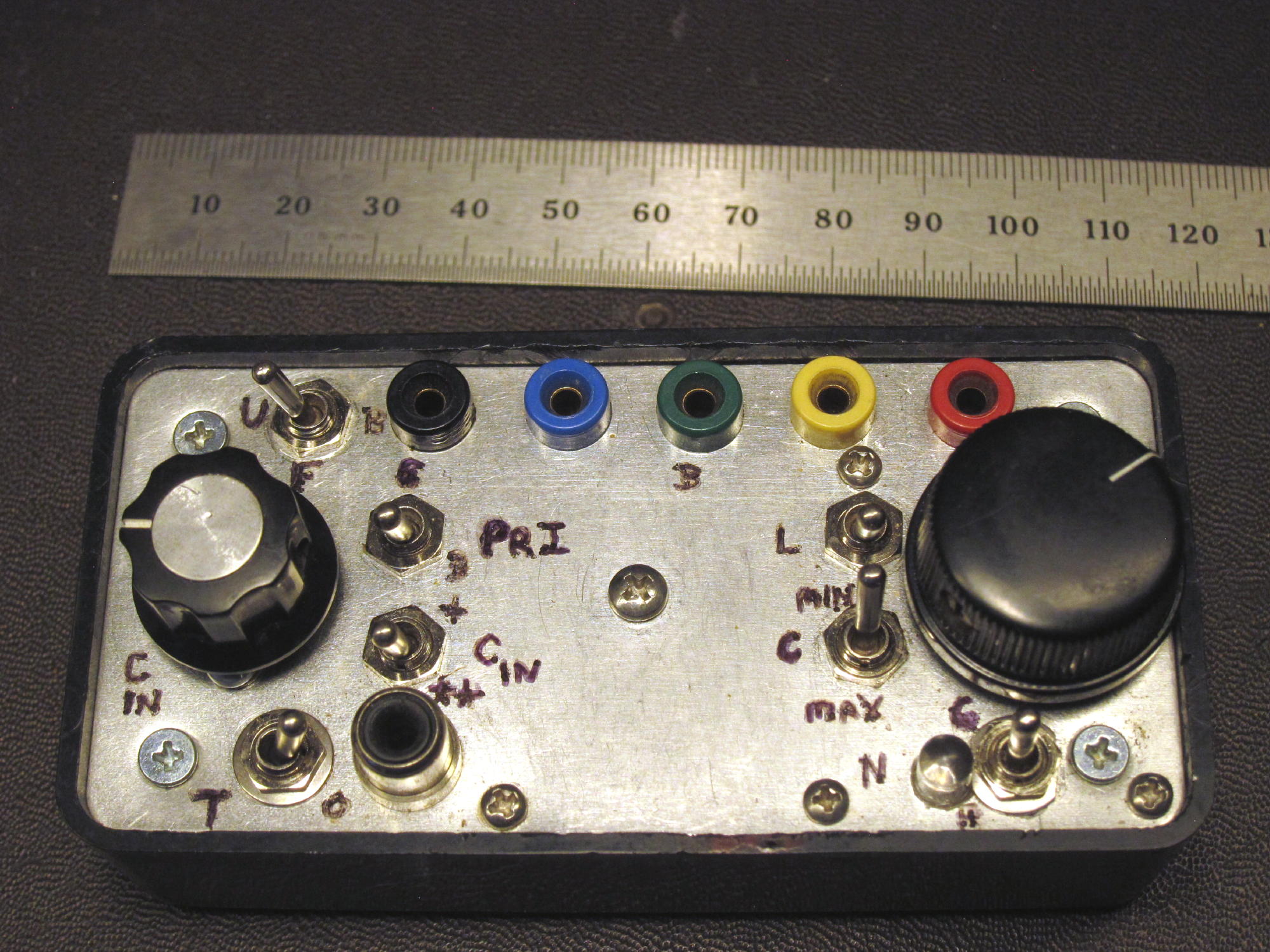
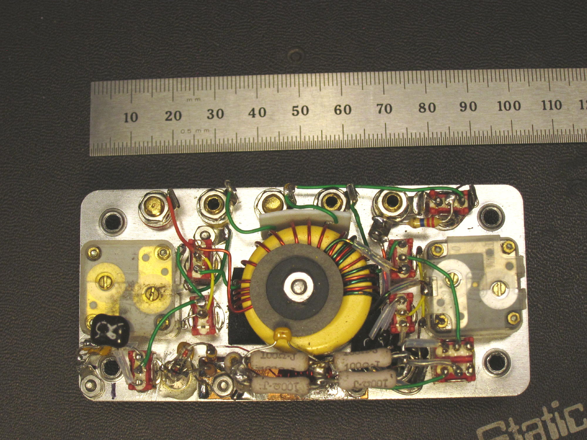
This photo shows three versions of the same tuner. the lower, left and right, is the original KI6J (one case open, one closed) good for ten watts. It has a built in (Tayloe) SWR indicator. Above in a tiny yellow container, is the very same tuner, but built without a circuitboard, and without a matching device. Truth is, you don’t need an indicator, as tuning band noise by ear works well, but I have the tinySWR indicator (weighs three grams) made available by DK3IT) built into my MTR radios. The original cased tuners weigh about 6 ounces, while my miniature version weighs a little over a half ounce. Size difference is also considerable.
SUMMARY: the original tunable version of an EFHW matching device by AA5TB is the best way to go. It uses #6 yellow core. #61 core material is better than #43 for the broadband matching device (by Parfitts), but the difference is less than a DB in our service and requires more turns for any given frequency. It can be smaller but doesn’t have to be smaller as my tiny version demonstrates.
Approximately 18,000 QRP SOTA QSO’s. Must be doing something that works 
73, Fred KT5X (aka WS0TA)
Fred and all,
Thanks for posting your EFHW tuners and comments. I can vouch for your results, after numerous S2S and chasing contacts with you from Colorado to New Mexico. I agree with your comments, which is more than I can say for many other comments posted here!
What stands out in this batch of postings is how many operators know little about how powdered-iron resonant tuners and ferrite broadband transformers work. This creates confusion and muddies the water for others who are curious about how to transmit better signals.
I wrote an article here covering the main points on Oct 1, 2018, a short distance up the page. It was too long for many, but I stand by it. I encourage most of you to read it - please consider copying it and saving it for a better time.
Here’s a bit more wisdom:
-
It is very reasonable to make our own efficient matching devices.
-
Really simple matching devices may not deal effectively with variations in both resistance and reactance (complex impedance) that occur in the real world of operating from mountain tops with compromised antennas.
-
Simple ferrite transformers, baluns, and similar fixed-ratio devices cannot possibly provide good impedance matches across several bands, with simple antennas, although they may work well enough to make numerous contacts.
-
Auto-tuners are a big step in the right direction, especially for those who want an easy answer.
Because I jump among several bands to chase S2S contacts, I use a homebrew tuner that has evolved from earlier versions. It has these features:
- A large T106-6 toroidal resonant transformer for high Q and low losses
- Two polyvaricon capacitors to permit control of both coupling and tuning for perfect matches
- Multiple taps on the transformer to allow perfect matches of both low and high impedances
- LED SWR bridge with tune-operate switch
- Switch to add extra input capacitance for wider impedance matching range
- Switches to add extra fixed tuning and coupling capacitors for lower frequency bands
- Switch to select the smaller section of polyvaricon tuning cap for less-critical matches at higher frequencies, or greater tuning capacitance for lower frequencies
- Switch for less inductance in order to cover 18 and 21 MHz bands
- Switch to choose primary turns - turns ratio - to cover a much wider range of impedances
- Switch to allow feeding balanced lines
- I run 10W from a KX2 through this tuner every time I’m on.
- Weight 5 OZ, 140 g
My tuner allows an end-fed wire 20M long to be matched nicely on the 60M, 40M, 30M, 20M, 17M, and 15M bands, with or without a counterpoise, with or without links (jumpers) in the wire.
With so many variables, such a device is not trivial to use. However, for my activations, it’s a miracle every time I get on the air and start band-hopping to look for S2S contacts, or to call CQ on a new band.
In the hands of someone without knowledge of the tuner’s theory and design, my tuner would be a bad experience on a SOTA activation. I’ve learned the normal settings for various bands, so using the tuner is trivial.
At first I didn’t realize how useful such a device would be for SOTA. The more that I broke my own rules, while using my tuner, I learned:
-
An end-fed antenna doesn’t need a counterpoise if the operator is near or on the ground
-
A counterpoise can be a fast, simple way to improve matching ability, or to add bands like 60M
-
An end-fed antenna doesn’t need to be resonant in order to operate efficiently
-
When using 10W of less RF power, insulated antenna wires may be run through live trees, run along the ground for a meter or so at the feed end, run over dry rock on a summit for more than a meter, run parallel to large rocks for many meters, and even laid right across the rocky summit ground, for many meters, when conditions demand such tactics.
-
Being able to force an antenna to work under less-than-ideal conditions, in unusual or “forbidden” configurations, provides valuable flexibility to deal with high winds, high altitude summits, cold, time constraints, or other people on the summit.
-
It’s OK to set up on a deep snowdrift, many feet above ground, using an end-fed wire and no counterpoise - the tuner will take care of that. Likewise rocks and talus, just ceramic blocks to RF.
Maybe I’ll write up my tuner, if anyone is interested. It’s certainly not an easy project, which is why it isn’t out there already.
73
George
KX0R
Good discussion on this thread! I totally agree with KT5X and KX0R on most of the info they posted. I’ve been using a trapped EFHW antenna for quite awhile now and I’m mostly doing the same antenna design as KT5X as I really don’t want to deal with any antenna/matching adjustments on an activation. As KX0R stated earlier in this thread…look up our stats and you’ll see we all make a lot of contacts on every activation…and this continues with the poor propagation these days!
Experimenting with antennas is great fun and I intend to continue that effort ;-).
73, Brad
WA6MM