EFHW Dipole - Mono Band Version

Hi Ed,

Most problems with antennas are caused by the builder making “improvements” and not making due adjustment. So your experience with the foam dielectric wasn’t unique in the field of antennas but well worth pointing out so others don’t make the same mistake.

I tried to make a 2 m version but it didn’t give an acceptable match. I suspected it was because the half wave radiator section did not have the assumed feed resistance. I got improved, but still not good enough, results by changing the radiator for a thinner wire. Should be able to fix that by adjusting the coax tapping point.

So not only do you need to check the VF and adjust the coax sections, you may need to experiment with the radiator.

For HF the radiator is electrically thinner and so is closer to the assumed resistance, hence the cut and play results reported.

73
Ron
VK3AFW

www.hb9f.ch is an alternative I found the other day.

You still need need to able to read German. Google complains the page is too large to do it for you.

73

Andrew

Hi Ron,
I was surprised with my first (RG-58) construction that ZERO “cut and play” was required. I was expecting to have to change it but in fact it was exactly resonant by simply using the values from the calculator. I have now “repaired” the RG-174 version, and will try to test it today, now that I have put the correct VF into the calculator.

73 Ed.

For a discussion in English, see this preso: http://audiosystemsgroup.com/VerticalDipole.pdf

This design is common for commercial VHF antennas. There, you’ll see a larger diameter rigid bottom element with the coax running through it. They are easy to spot. There are no radials and the “skinny top, fat bottom” elements are distinctive once you recognize the design.

Using a separate sleeve avoids the tradeoff between a resonant length element and a 1/4 wave section. Thanks to coax velocity factor, you can’t get both lengths correct with one length of coax.

These are sometimes called a “sleeve dipole” or “coaxial dipole”. There doesn’t seem to be an agreed-upon name for the design.

1 Like

Hi Walter,
Another interesting antenna - but not the EFHW Dipole(J-Pole) that this thread is about - I think this piece would be better for the discussion going on in another current thread on lighweight antennas - here:

Sorry, I misread the original article.

The sleeve dipole should be better in nearly all respects. Shorter, slightly lighter-weight, and less loss in the 1/4 wave section. The J-pole version is a 1/2 wave of wire plus the 1/4 wave of coax. The sleeve dipole is 1/4 wave of wire plus the 1/4 wave of coax. Since it is a 70 Ohm antenna, coax losses should be minimal.

wunder

I use a resonant end fed half wave on 20m from gwhip antennas. It fits on my 10m pole as a slight sloper. I’ve had a couple Americans on it whilst I’m on a summit with around 25w. Seems to work well.
Bit heavy for some people as it’s around 950g with its tuned circuut box on the bottom.

Great input Walter.

I wonder if we could arrange a regional antenna test, to compare all the various vertical antenna options - using the same location and same RX/TX equipment?

I have read that the J-Pole loses 50% of it’s signal because of its use of the stub to match the feed impedance - as you say the sleeve dipole coould be a lot better in this respect.

Oops, now I should have posted this to the other thread!

Ed.

Oops, the choke adds weight for the sleeve dipole, so it might not be lighter. But they are both vertical half wave radiators, so the performance should be very similar.

100g for my J-pole made with RG-179 coax and 24 awg insulated wire.

In theory OK for up to 200watts (but certainly OK for 25w).

Ed.

After sorting out why my lengths were not as expected (I was using RG-179 coax not RG-174 as I had thought) I have built three J-Poles that are resonant on 15, 17 & 20 metres … “but wait there’s more”.

Following some very annoying occurrences of the DX-Wire 10m mini-mast collapsing on me and it being too heavy, I set my self a “Scope of requirements” list which included using the 6 metre Lambdahalbe mast not the DX-Wire one (the 6m mast is less than half the weight of the 10m mast and shorter to carry). By winding the wire around the mast, it is possible to fit either the 15m or 17m antennas onto the mast. the 20m J-Pole insulated wire element however is too long to fit on the mast. In all three antennas I built the coax feed and stub / T-junction separate from the wire element and have 2mm gold plated RC battery connectors in between to connect them. This was initially done to make packing and assembly / disassembly easier as I can simply coil the coax part and the wire part winds onto a small former.

What to do about the 20m antenna? Perhaps I can run off the excess length from the top of the mast, Inverted-L like and guy it down on a thin cord at a distance? This would be one solution but another idea struck me - why not simply run the excess out at the bottom of the mast at about 1.5 metres high, over onto a walking pole or similar?

This antennas design is single band. the coax assembly is different for each band as is the insulated wire element, however I then looked at what I was thinking of doing for 20 metres and thought well I can do that for 17 metres as well and then just leave the 15m element on the mast and plug in extra lengths of wire element for the other two bands when needed. The major advantage of this approach is that I don’t have to take down the mast, coil-up the antenna and then put the mast up again with a different wire element, every time I want to change bands. Switching the coax assembly for each band is simple as I have theses as separate modules in any case.

The question was, would this 15m plus 17m or 20m extension actually work in practice - electrically apart from the extra connector it should look the same.

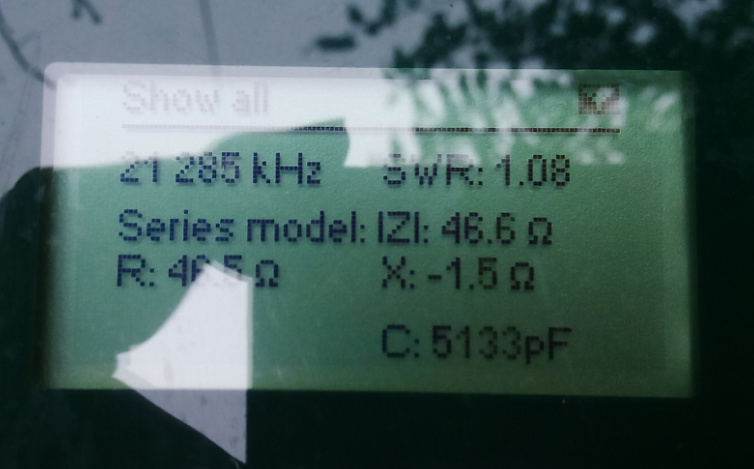
Today, I tried this solution and here are the resulting readings from my antenna analyser (sorry for the reflections):


15 metres - 21.285MHz 1.08:1 SWR

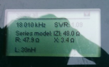
17 metres - 18.010 MHz 1.09:1 SWR (a small adjustment still needed on length to bring frequency up)

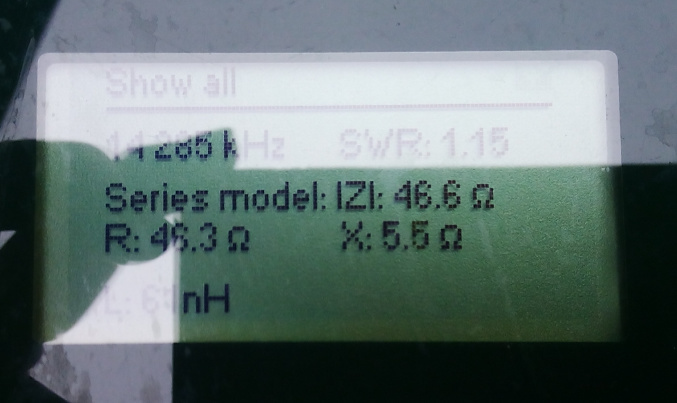
20 metres - 14.285 MHz 1.15:1 SWR

So you can see, it appears to work and … I have reduced the weight in the process,
Parts now to be packed -
3 RG-174 coax assemblies with short feed cable
1 extension BNC-BNC cable from short link to rig or amplifier.
1 half wave 21MHz insulated 24AWG element
1 short 24 AWG extension for 18MHz
1 short 24 AWG extension for 14 MHz.
and of course the LambdaHalbe 6m portable mast.

Now to try it out on a summit!

73 Ed.

2 Likes