Let me preface my question with a less-than-brief introduction… This will bore alot of you.
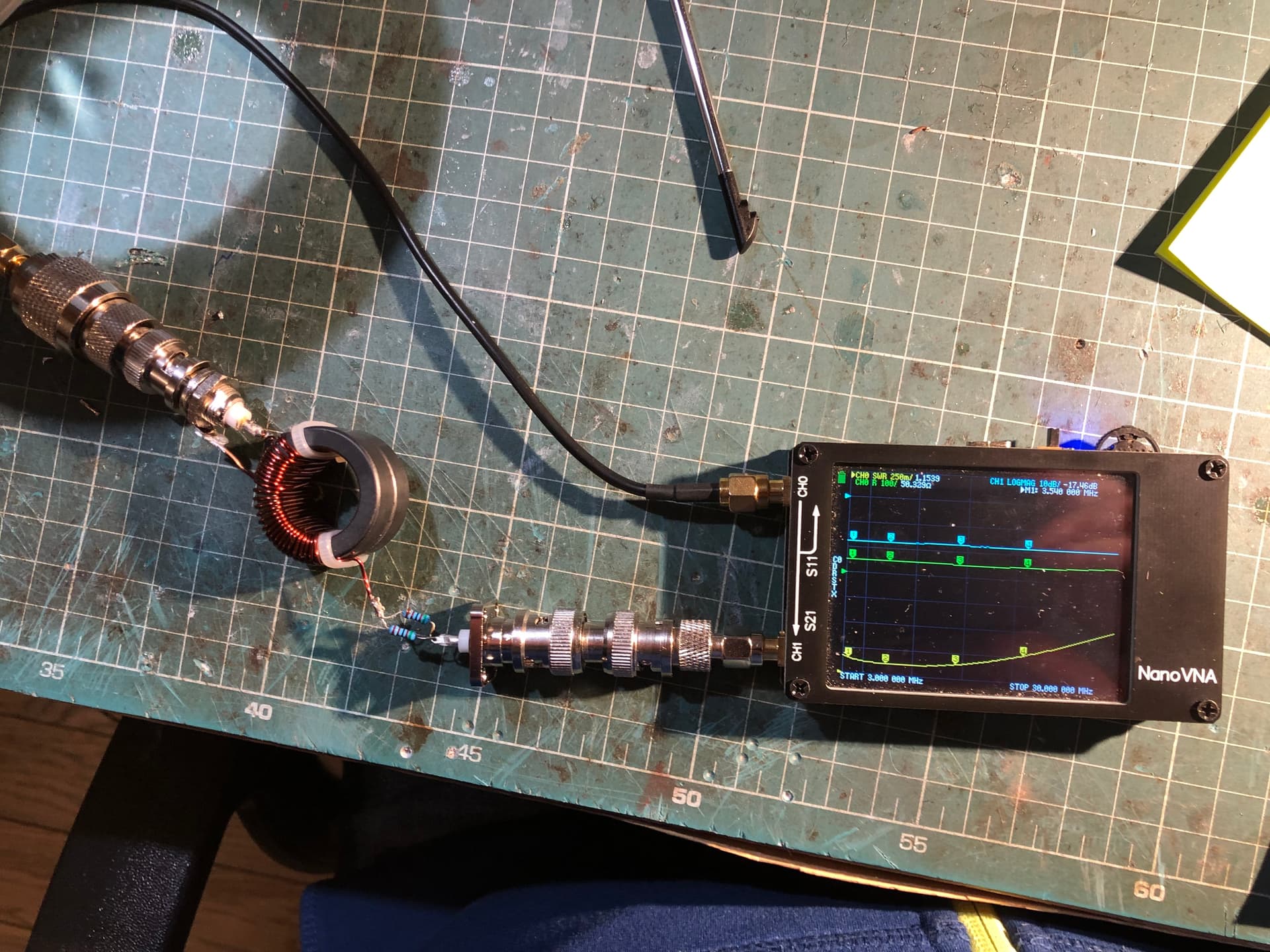
I have recently taken an interest in EFHW transformer winding and really enjoy the experimentation side of it. I most recently was doing testing on the 61-mix Fair-Rite 5961004901 double stacked, wound as autotransformers and was getting some truly exceptional efficiency readings with them on the NanoVNA. I found SWR to be unsuitable on the 40m band, but on 20m and 15m this transformer is a blowtorch with a 22/3 turns ratio. SWR and R values look great with a full length wire, and now I’m at the stage where I’d like to know what the power “rating” of this setup is, strictly for academic reasons as I rarely use more than 5 watts anymore.
I had read on Owen Duffy’s blog, and seen on several Youtube videos, that people state they will hook a transformer to a dummy load, TX at x-wattage for y-time, and record temperature increases on the transformer. My question is:
What are these folks using for a dummy load on the end of the transformer? Is there an ideal way to build an adjustable dummy load for when I’m experimenting with these different winding ratios (2450 ohms for a 49:1 vs 2700 ohms for the 54:1)? If I were to keep the transformers linked back-to-back as I do for efficiency testing and terminate with a 50ohm dummy load (wouldn’t need to purchase materials and could use what I already have), would that potentially skew the temperature tests on the first core?
Any assistance would be appreciated, as this is a niche request and I don’t exactly have anyone else to ask. I searched for a contact email for Owen Duffy to ask him myself but couldn’t locate.
From measured S21 value (total losses) you need to take away calculated value of -10*log((R+50)/50), where R is exact measured resistance of your resistor.
Result of the caluculation will be transformer losses, which you can convert to efficiency.
I would consider efficiency above 90% as very good result, above 85% good and more than 80% as average. Anything below 75% I would consider poor.
Yes I like that toroid a lot. It’s a great one, and it’s what started my interest in winding toroids. The 43 mix you mentioned is much better on 40m than the 61 mix I have been playing with, but the 61 mix is losing a mere .165db on 20m, And barely more on 15m.
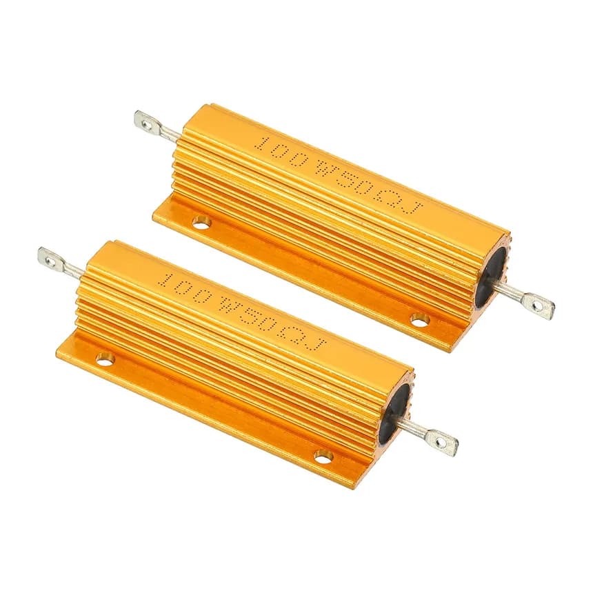
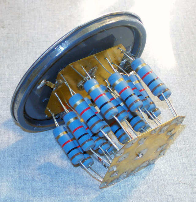
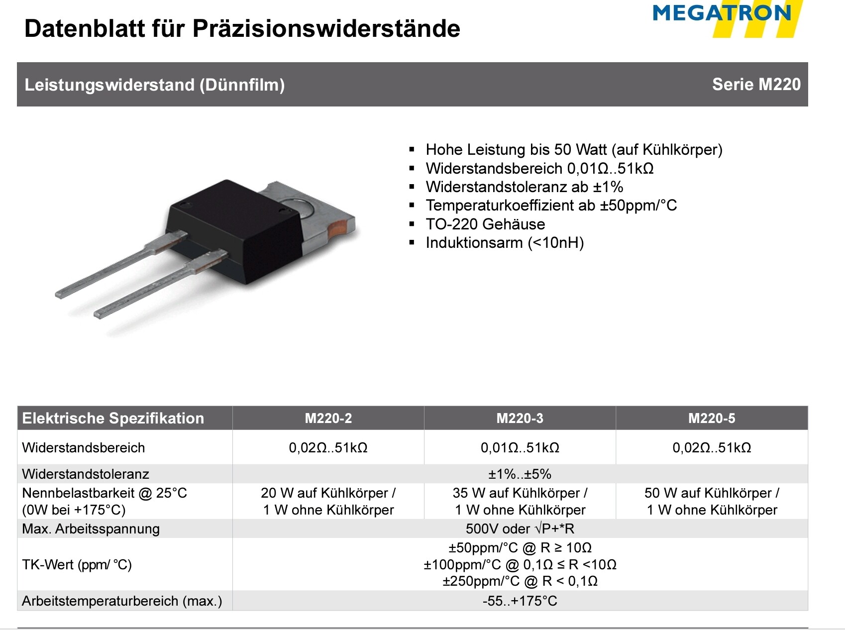
These are certainly wound wire resistors. These low-induction precession resistors in the TO-220 housing are ideal. I quickly found only a German data sheet.
I have experimented with both the resistor and back-to-back method, both seem to be completely valid methods for testing as long as they are compared exclusively of each other.
I’m really interested in seeing how hot this transformer gets if I transmit 10-20w for 30-120s straight but I don’t want to cause interference by transmitting into a “real” antenna wire.
Joe,
I prefer the back to back method. It requires less test gear.
For those new to this do as follows.
Build two identical units and connect them back to back. Use a decent 50 ohm load and power meter.
Then you can measure power in and power out. Half the difference is the loss in each transformer.
That also gives you an estimate of whether the transformer should stay cool or get hot.
3 watts will be warm to the touch and 10 watts hot. Both for key down for a couple of minutes.
A judicious use of your finger can tell if the transformer is getting hot.
It smoke appears or the winding changes color as you apply power you don’t put your finger anywhere near the thing.
I’d think each transformer would have half the total loss in dB, rather than in watts. So the calculation isn’t quite so straightforward (the first transformer would dissipate more power than the second).
But either method should give you the transmitter output power at which the transformer starts to overheat.
Dale,
Yes you are correct. Thanks. I was a bit offhanded
The the loss in the second transformer is less than the first one as it’s input is reduced by the loss in the first transformer.
If you apply 100W and the transformers have 90% efficiency then the input to the second transformer is 90 watts. The load will then see 90% of that or 81 watts. 10 watts are lost in the first transformer and 9 in the second. So 19% or 19 watts lost in total… If we assume half per transformer that looks like 90.5% efficiency instead of a true 90% efficiency. Pretty close but wrong.
Of course if the efficiency is lower then the difference will be greater. By using decibels we can get the correct answer.
If we convert the 81 watts to a ratio, 0.81, take it’s logarithm, divide that by 2 and then use the 10^x function on that to get 0.90. That’s 90% efficiency per transformer.
Most phones now have good calculator apps so no need for your computer.
We could produce a graph of efficiency of each transformer vs total % loss by calculating the output for transformers with efficiencies of say 50% to 100%. That avoids tripping ourselves up on the maths and decibels.
However I would probably have trouble finding that sheet but my phone is nearly always within reach.
The calculation IS straight forward. Assumed: two transformers back to back and a 50 Ohm dummy load. E.g. 100 W applied and 81W reach the dummy., thats 81% = .81 . Sqrt(.81) = .9 . No logarithm needed, just a simple square root, which can be found on ervery cheap calculator or app.
Certain for reasonably efficient transformers, the difference may be insignificant, and not worth reaching for a calculator. But not all published designs fall in that category. With 50% efficient transformers and 100 watts input, the first transformer dissipates 50 watts, the second 25, with 25 watts remaining to the antenna.
I also find my built-in “digital temperature sensor” (or “finger”) useful for such tests. (Not while transmitting, of course!) An infrared thermometer may prevent some painful surprises, however.
John,
Thanks for the quick square root solution. It hadn’t occurred to me that that’s what dividing the log by two does. Doh. Takes me back to form 4 and learning to use a 4 figure log book. Well spotted.