As I have understood it, in principal an Inverted-V HF dipole is like a straight dipole only with a centre support rather than two end supports and the radiating elements coming from the top og the centre support down to closer to the ground.
My question is the following:
Often on summits, finding somewhere to tie off the ends of the elements (or rather the cord on the end of the elements), does not allow the dipole to stay straight. In other words the antenna looks like a V in both planes - looking straight on and looking down from the top.
How does this configuartion change the transmission pattern? Does the antenna become more directional? If this is on 40m does it become less of an NVIS antenna (centre support is 6m AGL). Is the wire being straight critical to correct operation?
Is anyone, who is better than me with modelling software, able to model this scenario so we can see what effect this “double-V” configuration has please?
Yes, as always a portable location brings with it many variables.
Simplifying my question - is it “wrong” not to have the wire straight?
The background to this question, apart from knowing how an antenna on a summit “should” be set-up is that from my home location, I would like to install an NVIS 40m antenna to enable me to hear and work at least some of the German activators who my 40m horizontal loop antenna shoots over the top of. I am rarely able to contact someone less than 500 Kms away - whereas I can hear other chasers at a lesser distance to the activator, making the contact.
I can’t answer the original question, but I do have additional information. In “Antenna Physics; an introduction” by R.J.Zavrel, published by the ARRL, there is a discussion of the “near-ground inverted V antenna” on page 7.12. (over horizontal ground, of course).
Unlike a horizontal dipole, this antenna has both a horizontal and a vertical polarization response. So while the model shows a total field response that is nearly circular, this is made up of two figure-eight responses superimposed, one horizontally polarized and the other vertically polarized.
I don’t know enough about the propagation of HF to guess how this will affect the response of a particular receiving station, but it seems to complicate the notion of directionality if the radiated power is reasonably constant in all directions, but the polarization (and hence strength of the received signal) changes with direction.
The short answer is, don’t worry about it. A little more detail, since it isn’t high for the 7 mhz frequency, it is going to be largely omni-directional. Take-off angle is too complex, coupled to the nature of the ground, to project. As the legs of the dipole come closer together, impedance falls. It sure would rather not come closer together than 90 degrees. All that said, in my opinion after 500+ activations, well, after the few activations in fact, center fed is hard to deploy. I use an end-fed halfwave. Now the wire itself serves as the feedline, and the support pole can be astonishingly light weight. Mine weighs six ounces. 73 Fred KT5X (aka WS0TA)
I think the short answer to the question in your topic title is Yes, but it only affects the pattern slightly.
Recently the propagation has been very unfriendly to 40m and nobody has easily made NVIS contacts. It isn’t something that simple antennas can fix, in my opinion.
The only practical way of making those shorter distance contacts is to use bands that will allow those distances. Sometimes there is no HF band that will make a 100-400 km contact. And some activators do not have suitable VHF equipment, power levels or antennas to make a VHF contact feasible.
Hi Andrew,
I had also put this down to conditions to start with, until I heard other German chasers at about the same distance away from the activator as I am, working the activator successfully at S4 S5 when I can hear nothing. I have a low noise level here and a good receiver in the IC-7300. The antenna is therefore the most likely difference. In at least one case, the other chaser is using a simple Inverted-V dipole. The others I do not know but do not believe any of these chasers are using especially good antennas on 40m such as beams.
There are no mountain ranges between me and the activators to block signals.
I did have a dipole up previously however it was more horizontal than inverted-V and not laid out in a straight line - I did not hear these “close-in” activators with it. I have since read that for NVIS a “flat dipole” is not as good as Inverted-V - hence my query here about whether at best the Inverted-V should be straight when looked at from above.
Further reading about NVIS suggests running three “reflector” elements about 2m apart under the dipole to further increase the vertical angle of radiation, unfortuantely I don’t have the space here to do that.
If it is say a 7 MHz dipole and you are using it on 7 MHz then the change is SFA (Small Finite Alteration). Don’t sweat about it.
The average height above effective ground is the major factor. Tilting the vee over to fit the dipole in is OK. Just get the centre and the ends up as high as practicable.
The ends do not have to be close to ground level. Indeed there are many good reasons to have the wire no less than 2.5 m above ground especially for a home antenna.
If you run the antenna on its third harmonic the tilted over configuration will be a tad more directional than if it isn’t tilted. Maybe that is useful and maybe it isn’t.
Antenna modelling, flat earth or not is fine, especially for NVI. It just confirms that the distortion in the pattern can be more than compensated by a small lift in average height. As I think you are talking about a home antenna the knife edge QTH does not apply.
I have used various antenna including the G5RV, doublets, link and trapped dipoles in the inverted Vee tilted over configuration over some 40 years. No one has noticed. At home the ends are 6 m agl and in the centre 12 m agl. My back yard and YF condoned mast placings limit me to about 115 ft of wire in an inverted vee tilted over shape.
Even on 80 m propagation can be significantly different at times over only 6 km or so. It is much more noticeable on 40 and above. Another chaser will sometimes give out 5x5 when I have 1x2 but often 5 minutes later I have 5x5 and he has 1x2. When sunspot counts are low the propagation footprint moves about more noticeably.
Having a temporary vertical antenna may be useful for comparison. For receiving only just put a squid pole next tho the shack window and run an 8 m wire to a change over switch. Proper earthing and matching would be required for transmitting but for a temporary receiving setup only, these can be dispensed with. The S/N ratio is more important that the signal level.
One advantage of running Inverted V i have found years ago whilst on another band.
I made one stuck it up about 20ft and two of my friends did the same one 3 miles north of me and the other 20 miles south of me. Tuned straight fed from coax into the V it self tuned wires to the band required.
Interesting thing was my friend north of me slight increase in signal but we were strong to each other in first place and friend to south jumped from S4 to S9 and we both had beams and vertical antennas yet this V made that much difference. Yet another friend made one 15 miles of me two whom struggled to hear in first place also shot up to S8.
But what me laugh any mobile stations with in one mile or less I lost there signals till they were more than a mile away and the pain in Butt station i had 2 mile miles away his signals dropped down from S9 to S5 and hear my friends further away better than the so and so station to his pain and my pleasure so to speak.
But to get better localized signals like Ed talk about of less than 500km you need that CF to climb to freq your operating off say namely 40m 7mhz. My 40mb full wave loop is only 23ft of ground. So should be good NVIS antenna. BUT only works if the CF is climbing above 4mhz pushing 5mhz, i get 500km to 400km 6mhz around 400 to 300km and above 6.7 and above 7mhz the locals get really strong with me from 20km to 200km and certainly not ground waves.
We call it inter G prop on 40m But because am down south so much and so far away from Scotland NI even at 5mhz i can reach those areas no problems as others north of me will struggle as there distance apart is far less higher up country you go.
But on 80m its good for getting out but poor at RX because its prob to low.
Feel Verticals do well on Summits even with low output as am restricted too but rather enjoy the challenge. Yet Closer than 500km skip on 40m is going to get harder as the cycle declines as noticed of late.
So if you can get the rest of your 500km range people to convert to Inverted V antenna you be surprise whom you can reach, but both stations in my experience have to be on it.
But end of the day love the striving of to improve what we have and more and more power is not always answer for if no prob no one is getting through yet find build better antennas makes my 10w work harder and same for summit operators to whom not have pack mules also using low outputs.
Hi Ron,
as always thanks for the wise words. My planned home installation will indeed have the ends of the wire at around 2.5 metres off the ground - the centre being at about 6-7metres high (I’ll see if there’s any way to get this higher as you say it is one critical factor). OK that a small bend in the line of the antenna is not going to make a big difference - that was one of my main concerns.
The fact that propagation can be so critical over only slightly different paths on the low bands is news to me. Perhaps this, as you say, is more noticable when band conditions are bad, as at present. This could well explain why others are working an activator about 350Km distant when I can’t even hear him.
I will still put the 40m dipole up in addition to the loop however so that I can compare. I also have a mount where I used to have my multi-band vertical and I could put that up again for comparison, however it may now be affected by the nearness of the other horizontal wire antennas. Compared to the loop, the vertical previously was both noisy and deaf, but at that time I was trying for DX, perhaps it’ll be better for the 50-400Km range but I suspect not as verticals tend to be low radiation angle antennas.
All of the above is awaiting the snow to go away which we got earlier this week!
I’m sure propagation variation is the main reason you could not hear the station 350 km away. We are used to it on the high end of the HF spectrum but I’ve experienced it often as low as 3.5 MHz. It’s frustrating to hear your (relatively near) neighbour getting Q5 copy when you are struggling to hear anything at all. Often the signal will come out of the noise for long enough to complete an easy QSO but sometimes it doesn’t. Que sera sera.
The loop is a much better receiving antenna in the suburbs but is directional. If you can peak it then it will be a good reference. The vertical is simple but will pick up all the local noise very well. Being non-directional it would tell you if the absence of a signal was propagation or an antenna null. It’s not good for stations closer than about 250 km. The loop should be OK for most distances, although again like the vertical it is not very good on very short skip.
Providing the nearest antenna is more than several loop diameters away the interaction should be negligible. Think of the dipole wire as a very loose coupled distant turn on the coil. The orientation and distance affect the slight coupling which I would ignore.
Our first significant snowfall in the alps for the year has been and melted away. The weather is near perfect for activating. It’s also perfect for painting the outside of the house and cutting the grass.
Hi Ed and all
The NVIS propagation is at present down at between 3 and 4 MHz here in Scotland. I have great difficulties to hear any UK stations, although I can hear some near EU Continentals working UK stations on 5 and 7 MHz bands.
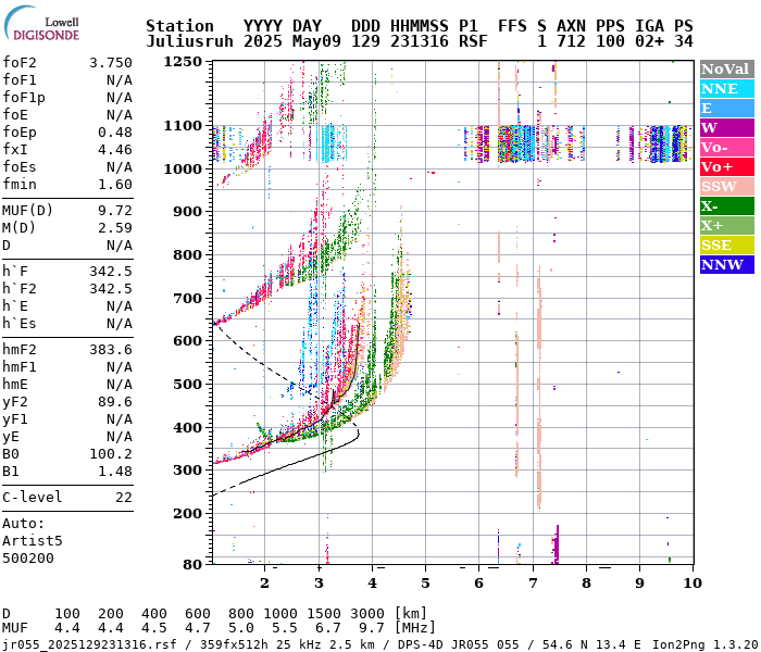
I have a look at the Chilton Ionogram; View Latest Ionogram;
at times and it tells me that NVIS propagation (f2F0 freq) is barely up to 5 MHz at present. Propagation on 7 MHz is beyond 800 to 1000 km for most of the day i.e. I cannot work any UK SOTA stations on 40M except under exceptional circumstances such ar aircraft reflections etc etc.
My aerials, dipoles and verticals, are not able to compensate for that kind of propagation; I wish they could but laws of physics are against me!
73
Ken
Thanks for the comments from you and others - Karl already pointed me at the Chilton site, but it requires an account to login to get access. I believe this is data from the equivalent site in Germany -
It seems to agree - short range contacts possible on 80m but not 40m.
In reply to Ron - for clarity to loop I refer to is a Skyloop - full wavelength horizontal loop (not a magnetic loop), so locating the vertical or other antennas several “loop diameters away” would be way outside of my property unfortunately. The loop should be omnidirectional on it’s resonant frequency I believe - only on multiples of the resonant frequency does it become directional. the idea of comparing what can be heard on one antenna (e.g. a vertical) compared to the loop and compared to the planned Inverted-V dipole is a good idea, as you say if one antenna can pick up the activators signal and the others not, there may be an issue with the antenna that cannot hear it. In fact this gets me back to one of the reasons I want to put the dipole up and why I asked thois question originally.
Thanks all. Now the sun is out and the snow nearly completely gone, tomorrow could be “antenna day”!
Select Paris for a rough view. At 1500Z on 7MHz you’re looking at 600km minimum.
I did have a version of the db that would draw a LAMP chart from view point of any summit so you could see if you were in range and what the chances of a contact would be but Brian G8ADD told me not to bother.
Thanks Andy,
that Aussie Government site is a real treasure, if you know what you are looking for!
Of all of the locations available, strangely, the one for the UK cadet force (with it’s 60m 5.3MHz data included) is the closest to the values that I read from the bottom of the screen of the Ionosonde in Germany.
Sounds a great idea to be able to look at which bands from which summit would cover which area at what time of day - and not only for the activator - rather for the chasers as well.
The Australian space weather services actually gave a well attended lecture at the Wyong Field Day (Radio Rally) of the Australian club I’m a member of - the CCARC. Shame I couldn’t get over to see that !
In practice, the orientation of a inverted V has very little effect on its pattern because the kind of inverted V we can actually put up on the summit of a mountain will be so low that it will be basically an omnidirectional antenna with a lot of its power being radiated at a very steep angle (a cloud warmer). It is still worth putting up, in fact the vast majority of ham installations are just that sort of antenna. Tha is the real world.
If you could put up your inverted V 10 or 20 meters high, yea, it would have nulls off the ends and have a little lower vertical angle of radiation off the sides, but real hams with real installations can rarely do that, especially in the middle of a snow storm on a windy mountain top!!
If you are installing an inverted V at home, there is tons of literature out there to help you understand the trade off’s. But, in real world installations, it is fun to run computer simulations, study the literature, carefully understand radiation patterns, then put up the antenna where the tree is!
From my experience in the real World, not with simulators, which I’ve never used, the main factor to enhance a dipole performance in a given location is height, the apex and the ends height a.g.l. Basically, the higher the better as long as the angle between the two wires of the dipole at the apex is about 100 degrees. Then, the wires fully straight or bent to accomodate certain restrictions in available space, I think that doesn’t affect the coverage pattern. When I lived in Aranjuez-Madrid, my 80m dipole had one of the wires bent at 90 deg. and the other one bent twice at nearly 90 degrees due to lack of space. However, I managed to get the appex about 15m a.g.l. and the ends at about 5-6 meters a.g.l. which demontrated to be good enough for a great performance, providing glorious pile-ups of JA’s and USA on that band. I need to say those were the good propagation years, though. 2006 to 2012.
Regaridng other nearby colleagues copying what you don’t copy is something I’m very used to. As you know, we have a group of SOTA chasers in the city of Pamplona and we often see one of us copying some weak activator while the others don’t and in a matter of few minutes, things sometimes change to the reverse, copying those who previously didn’t and not copying those who had previously copied and worked that weak activator.
Propagation is a really amazing thing and I believe we’ll never fully understand what it does and how the waves travel to our antennas.
My advise is put that dipole as high as you can or are allowed to and try it out. You’ll surely have fun out of it and no doubt you will learn things by using it and comparing it with the loop you currently have and your neighbour hams antennas.
Good luck with your project.
73,