Hi everyone,
I just completed the description of a delta loop for 20 metres. You can find it here:
I’m planning to use it during the JA/VK/ZL <> EU S2S event.
73, Roman - DL3TU
Hi everyone,
I just completed the description of a delta loop for 20 metres. You can find it here:
I’m planning to use it during the JA/VK/ZL <> EU S2S event.
73, Roman - DL3TU
Thanks for taking the time to document this Roman. I am planning on building a static-vehicle based delta loop, but I hadn’t considered it for SOTA. What I’m finding with my inverted-V is it is much easier to setup standalone than attached to the car - too easy for sections of the squid pole to drop down and/or wires get tangled.
Please keep us posted with how you get on, and good luck!
Mark.
M0NOM
Thanks, a topic I’m very interested in and an antenna I’m thinking about trying. Please let us know how it performs.
What I’ve been thinking of doing myself is to center feed the delta loop (horizontally polarized) through a balun (to match the higher impedance), and position the antenna near a substantial down-slope (in the favored broadside direction) to make it effectively a highly elevated antenna to lower the angle of radiation. Should show several +dB gain advantage over the vertically polarized delta loop.
73, Barry N1EU
Hi Barry,
Even simpler than a Balun would be a Q-section of 75 ohm coax of 1/4 wave length. That’s what I come back to using on my 20, 40 & 80m horizontal loops (which are effectively a sister antenna to horizontal Delta loop). I’ve tried Baluns and feeding with ladder line and every time, I come back to using the Q-section - it receives less local QRM and covers multiple bands.
Good luck to you and to Roman and Mark for the antenna experiments!
73 Ed DD5LP.
Coax matching xfmr is a good alternative. I’m thinking of nested 20M and 17M elements fed together and the balun is a better choice for me. And center feeding is also the better choice if you’re feeding two or more nested wires together.
That being said, I’ve been doing some modeling and another configuration for 20M loop that looks good and easy to erect is an isosceles right triangle: 6.7m wire vertically up the pole, 6.7m wire horizontally out from bottom and 9.5m wire as hypotenuse connecting the two. Feed it at the acute corner away from pole. It has nice 50 ohm impedance and low angle radiation.
Barry N1EU
This!
Special activation events like this and the NA<>EU day, plus local association activation days (such as thre recent OE day) add a nice variety to SOTA. These events give a range of activation options such that you can have a lot of activation fun with just handy as in the OE day or you can plan to put a more significant antenna on for a special event like VK<>EU. The rest of the time you can set the target lower and use simpler to setup and lighter to carry antennas for “ordinary” activating.
Anyway, thanks for the excellent write-up about the antenna Roman.
…well, thanks for the feedback! (where do I start now?)
Andy, it was exactly my intention to use an antenna with some gain for the S2S event. Signals will be weak anyway considering solar activity and low power/ simple antennas on both ends of the path. During the “usual” activation one can use whatever simple/ lightweight antenna and rely on the antennas of the chasers 
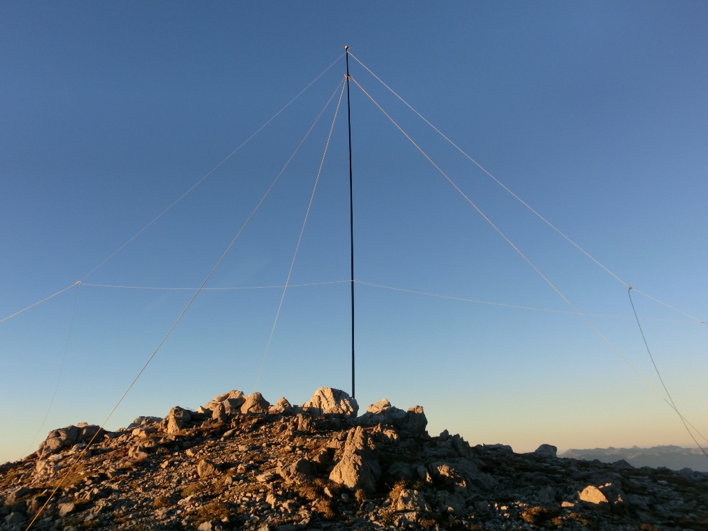
The set-up is tricky as there are guy wires (at least one) running through the loop. You need to carefully plan each step or you’ll do the set-up twice (I went through this several times already).
Barry, Ed, there are a couple of advantages of the shown design compared to a “classic” delta loop:
I’ll surely post my experience here after the S2S event. So all we need now is acceptable weather, low k- values and two or three sunspots.
73, Roman - DL3TU
Barry, whats’ the radiation pattern for that set-up?
Richard // N2GBR
How does this compare to a vertical with ground plane? I’ve built one to go with my 10m pole - the three radials are also the guy wires, so it’s easy to erect. I admit I have only tried it in the back garden where it seemed to work well.
@N1EU Can you share the MAA file ?
Thanks,
Petronel
I have both a vertical delta loop and a vertical groundplane with radials for 40 meters at the home QTH. Both are elevated about 12 meters. I am very familiar with the modelled patterns because I designed a phased array using them that has some gain to the north for NA and EU. The patterns are quite similar, omnidirectional within a few dB (the VGP has a much deeper null directly overhead) but the proof of the pudding is in the using. Sometimes I can hear better with one or the other, and noise is a bit higher on the VGP, but the best results most times are with them phased. SWRs and bandwidth are likewise in the same ballpark. All in all, making the DL was a lot easier than making the GP.
Steve in Okinawa
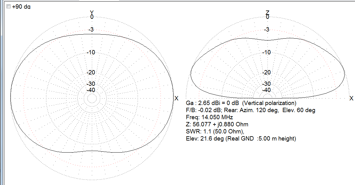
The reflector reformats the MAA file punctuation so I would need a place to upload the MAA to. Here is a screen shot that will allow you to easily do it yourself:
‘’'
Here’s the MAA file contents:
*
14.15
***Wires***
3
0.0,	0.0,	0.0,	0.0,	-6.7,	0.0,	8.000e-04,	-1
0.0,	-6.7,	0.0,	0.0,	0.0,	6.7,	8.000e-04,	-1
0.0,	0.0,	6.7,	0.0,	0.0,	0.0,	8.000e-04,	-1
***Source***
1,	0
w2b,	0.0,	1.0
***Load***
0,	0
***Segmentation***
800,	80,	2.0,	2
***G/H/M/R/AzEl/X***
2,	2.0,	0,	50.0,	120,	60,	0.0
Barry if you start with 3x back-quotes (this character ` ) then hit return then paste the file then hit return and type 3 more back-quotes the pasted text should be shown verbatim and unformatted.
Hi Barry,
could you add info about heigh over ground (from the lower horizontal wire) in your simulation model?
Thanks, 73 de Ignacio
I think the simulation was with 5m height, but it looks similar with 2m height. The effective height will be higher than the physical height of the wire if there is a downward slope in the broadside direction.