I’m being forced to buy new coax as I have discovered mine is corroded quite bad ( not showing major signs in use though ! but it was rubbish anyway and is at least 20 years old !) I’m looking to use some higher quality coax but generally this is thicker and less flexible so to get around this I was thinking of using a short patch lead of thinner coax, Is this a bad idea ? Am I better off going for a smaller diameter coax in the first place and accepting the extra loss to avoid using two types of cable ?
If you’re talking about HF and SOTA, I don’t think the smaller size coax is going to have enough loss to worry about. I wouldn’t think you’d have a very long run for a SOTA activation?
73
K6YK
Assuming that both cables have the same characteristic impedance eg 50 Ohms, there is nothing wrong with joining them.
The critical point is the join. It should ideally maintain the 50 Ohm characteristic. So, use good quality connectors eg N type or BNC (not PL259s) and make sure each one is chosen to fit the cable size.
Its not the end of the world if the join is imperfect, but - especially if the short patch lead happens to be an odd multiple of quarter wavelengths - you could end up with a bit more loss than you expect.
Putting that in perspective, lots of people use PL259s, and route the cable through an A/B switch of dubious quality, and still manage to enjoy some contacts!
At VHF, and especially UHF, it may make a difference.
On a SOTA activation, the cable lengths are likely to be relatively short, and losses should be minimal, even with relatively small cables. For a home station, where you may be using more than 10m of cable to reach a UHF antenna on the roof, then using a lower loss cable makes sense.
But as others have said, there should be no problem with joining two different types of 50 ohm cables together using standard connectors. That’s not uncommon, when someone wants to use larger (stiffer) low-loss cable in from the antenna, then a more flexible jumper cable to allow equipment to be shifted around on the operating desk.
Thank you for the replies everyone, the main thought was my home station with a max frequency of 70cm ( should have said this first time round), I need 15 meters of coax, only have 1 watt output and am limited to a simple 2/70cm antenna (homebrew) as I’m trying to keep it fairly covert. I’m presently using a 2 meter dipole for both bands, it was in dual band flower pot arrangement but I discovered it worked better as single band flowerpot antenna ( less the phasing shield around the feed centre) but used on both bands with very old dodgy cheap Mini 8 cable. The good thing is I’m starting from a very low point and it just about works so it should be really easy to make it better !
For 2m and 70cm I would go for the best coax that you can afford. Personally I would use a semi-rigid 7mm cable like Aircell 7 or 5D-FB as an absolute minimum, preferably a 10mm semi-rigid cable if you can afford it. You will need to obtain the appropriately sized connectors for the chosen cable and as others have suggested, BNC and N types perform better at 2m and 70cm. The more connectors you have in a cable run, the more the potential for loss of RF and also failure of the cable as a whole.
You noted that you had corrosion with your current cable which would suggest water has been getting in, most likely at a point where a connection is made. Decent quality self-amalgamating tape is essential for sealing around connectors to keep water out of cabling, suitably protected from UV by electrical tape on a home installation. I don’t bother with the electrical tape covering on my portable cables as they are not permanently exposed to UV.
Home stations do it all the time, including for VHF / UHF
Thick low loss coax from the shack up the tower. Thinner / more flexible coax as the rotator loop.
Follow others advice in this thread regarding connectors, etc.
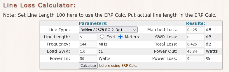
I have just measured the loss on a new piece of cable I will be using for 145Alive.The cable ia 5m long and good quality RG213 The measured loss is 0.5dB. This is good cable where you cannot see the dielectric through the braid. The simple cable loss, 50W in, 44W out.
I used to carry RG-213 up summits, but soon discovered 5D-FB cable which saved a lot of weight… and I believe a fraction of a dB in terms of loss. Of course for the home installation, the weight of 213 is not an issue and the fact that it is available and at reasonable cost makes it a decent proposal.
Ideally you need to buy enough to go from the shack to the antenna. Maybe an N type male would be best for the size of cable, so a patch lead with an N type female on one end and whatever plug suits the rig on the other. I suggest N types as their threaded collar connection method is better than a bayonet connection, as in BNC.
When I originally set the coax up the easiest way was to pull it in around a downstairs window frame where the copper landline was routed, This was a real struggle and I have since found I have damaged the outer jacket of the cable (or it was originally damaged !) It then runs up the outside of the house and was originally sent back into the loft via a skylight ( its not sitting above the skylight) I’m guessing rain has run down the cable into the damaged part. I have now decided to route the cable up the corner of the room through my lads bedroom and then into the loft keeping the coax all cosy and warm tucked away behind ducting . I intend to make this big enough to accommodate more cables should I need/want to. This will also avoid a couple of sharp bends, I intend to use FZ400CU ULTRA FLEX as it has roughly half the loss of RG213 at but is not majorly expensive. . As I only have about 800mw at 70cms and 1 watt at 2 meters I need every bit I can to reach the antenna. The antenna will be in the attic as I can get access to experiment with homebrew designs, I just need one that will give me some gain on both bands !
Brad, I didn’t know you were talking about running QRP when I answered the first time. I’ve joined a lot of different cables together over the years without any serious consequences, but I never run QRP. Power overcomes a lot of mistakes!
One story I jjust have to tell from back in my younger and poorer days: in the 1960s I lived in an apartment in Oakland, CA and was newly married without a lot of extra ham radio cash. I built a 2-meter
AM transmitter from old FAX machine parts, except for the coils and tuning capacitors and the 5763 final tube (valve). There were virtually no FM repeaters or FM activity at the time, everybody was on AM. This transmitter had enough output to light a #47 pilot light bulb to some brilliance. So, I took it home and then had to conjure up an antenna. I had a receiver (HF with a converter for 2 meters). I made a collinear vertical on a wooden stick, a balun so I could feed it with coax. I found a small roll of RG-174 coax at work that was surplus and going into the scrap bin and took it home. The run from my bedroom hamshack on the first floor of the apartment house to the middle of the third floor roof had to be at least 70 feet! What did I know? I used that RG-174 for the run, AND IT WORKED! I was able to contact local stations in nearby towns and there was an AM
repeater (Yes, there was!) about 40 miles away and I was able to reach it and work stations all over the area, maybe up to 100 miles. I checked to see, and the loss is 9.3 dB in RG-174 at 146 MHz it’s a lot. I’ll never forget that setup and how well it worked. I wish I still had that transmitter.
So much for the “good ole days”
73
John, K6YK
This is a foam dielectric and foil screen cable. So make sure you remember the minimum bend radius and don’t exceed it or, sadly, you will do irreparable damage to the cable. Gentle curves are fine, it’s the sharp bends that are a no-no.
You ought to see the corner of my shack which is on the first floor. There are loads of cables snaking up into the roof space… and 5 years on I have not fitted the planned 50x50mm conduit. The XYL has not complained… yet!
The 2m high power set up used for meteor scatter uses a length of LDF2-50 on the TX side (RG-8 patch lead). A longer length of RG-8 is used on the receive side which goes up into the roof space and connects to a shorter length of LDF2-50 in the roof space. Both these LDF2-50 runs exit the eaves and terminate about 1m above ground at the rear of the house. As I only put up my 2m yagi for meteor showers, I use temporary H100 cables from the LDF2-50 tails to the masthead preamp/relay unit. There is then a short length of RG-8 to the driven element along the antenna boom. So 3 types of cable in use there. All connectors are N types.
The 2m and 70cm low power rigs feed verticals in the roof space via Aircell 7. Then there is another length of Aircell 7 feeding a coaxial relay in the roof space which is connected to a 6m delta loop and a 6m wire moxon. A cable to power the relay goes up by the coax cables. A further cable (RG-58) is used for HF, so 6 coax and one power in total.
Excellent choice. Less loss on both transmit and receive. The lower the loss on receive, the better the noise figure.
All the best with running QRP and experimenting with antennas.