Afternoon All
I have been using a HF packer 2 amp for my last handful of activation’s.
The amp works well, but only carries two sets of LPF, currently 60/40 and 30/20
17m was in good shape yesterday, but i couldn’t field change the filter, and low power from the KX2 was not quite enough (SSB).
Has anybody tested the upper and lower operating voltage levels, or monitored the spectral purity of the output?
I dont have access to my lab equipment where I am at present (It is in storage), so any findings/advice appreciated, particularly around the lower voltage that the Chinese amp will still operate to.
My SOTA go to battery is the 4200 4s2p favored by many.
Works well with the KX2 and HF Packer 2, or 817/HF Packer
I once had a complaint about some splatter on 60 ( I think my signal was 59 + 20 and some distorsion was visible on a scope), since then have only driven it with 2.5W and have had no problems and the battery lasts a bit longer!
Unfortunately I can’t answer your question relating to the lowest voltage that a MX-P50M will run on, but it would be interesting to test this out. From experience, the normal operating range of a 4S LiFePO4 is fine for the amp and I certainly wouldn’t want to take the battery beyond its voltage plateau. Three hours on air last week only required a little over 2AH to recharge my 4.2AH LiFePO4, but like Paul I usually run my amp at 25W output (2.5W drive) to conserve battery power. Reports on air have been excellent at both 25W and 45W output levels.
To date I haven’t found a decent review of the MX-P50M which is surprising seeing that the amplifier has been around for a number of years now. The design of the package is obviously based on the 13.2V standard for convenience with it being designed primarily for portable use. The physical size of the heatsink is undoubtedly a limiting factor, particularly as the efficiency rating of the MRF186 is specified at 30%. The spec sheet gives an output rating of 120W PEP on 28V at 960MHz, so the device is being conservatively run, but it still gets quite warm running at 25W output.
Thanks for the link and observations Paul.
I dont run flat out either (Unless its the BY I managed to crack a pile up for), 25 - 30w works most of the time.
As soon as the new house is ready, I can dig out my test equipment and test it properly.
The HF packer 2 is a nice amp, but weighs a lot more than the Chinese amp, it will comfortably run 30w data all day though if you have the battery capacity.
T
Hi Gerald
Interesting points, thank you.
I run the same battery as you, and sometimes for long activation’s the 8400 version, though this is very heavy.
The 4200 runs around 13.2v +/- and has a low voltage alarm fitted to it to prevent problems.
Good to hear the MX amp will still function at this input voltage without splatter, that is what I wanted to hear really, rather than having to carry my old 5300 Lipo brick around with me.
I will test the low end operating voltage when the lab gear gets out of storage again and report back.
In use, I found mine was happy with 2.5w drive for SSB using the 817, speech processor/compressor and resonant antenna, I did feed it with a 5300 Lipo and dropper diode/s though so wasted energy in heat.
73
Tim
FT817ND and MX-P50A wired in parallel from variable 30A PSU.
40m filter manually selected on Amp. No absorption Wattmeter
available so used YF-3 VSWR/Wattmeter set manually to 50W* (FSD)
with 13.8V input to combination and FT817 set to 5W. 100W dummy load.
Results:
13.8V into combination:
FT817ND-5W. O/P: 50W*. Current drawn by combination approx 6.5 Amps
FT817ND-2.5W. O/P: 36W
FT817ND-1W. O/P: 13W
11.0V into combination:
FT817ND-5W. O/P: 30W. Current drawn by combination approx 6.0 Amps
FT817ND-2.5W. O/P: 23W
FT817ND-1W. O/P: 12W
LOW-VOLTS Tests with 5W input from FT817ND:
10.6V Applied to combination: O/P was 27W
10.2V Applied to combination: O/P was 25W
Rapidly decreasing O/P until 9.0V reached = NO OUTPUT from combination at 9.0V
Notes:
Voltages higher than 13.8V not tested.
Amp is rated at 45W but with no exhaustive spec sheet available, unclear under what circumstances?
For ease I assumed 50W O/P at 13.8V/ 5W input and set my power meter to FSD accordingly - just for convenience.
Readings had to be taken quickly so as not to heat system unduly.
Current readings are for combination and for guidance only.
Most of the time I use 2.5W input but have had no complaints when using 50W. I do not have the equipment for spectral analysis but hope this helps.
Thank you John
That is the low voltage testing information I was looking for.
I should be fine with the Life 4200 and save some weight over the HF Packer and 8400.
Thanks for the results and testing.
73
Tim
G4YTD
Hi Tim,
I’ve been looking at the Chinese HF amps lately myself and have a 100w one on order. In the majority of the sub €200 units they do not have Low Pass Filters fitted, but several have pad where you can take the signal out to your own LPFs or a bought LPF board. Most of the amps 45w, 50w, 70/80w, 90w, 100w, 150w and 180w are available either as a DIY kit or assembled. Assembled also meaning the inclusion of a heat sink and sometimes a fan, which isn’t included in the kits. If you shop around you can get the kit for the 70/80w amp for less than €20! The relay switched LPF board (that you really need for these class AB1 amplifiers) can cost up to €40 built or around €25 as a kit.
As for voltage. One of the amplifiers needs a 24v supply and 10w drive to give the maximum output (that was probably the 180w one) at 13.8v I think it gives about half the power. The 100w model I have ordered needs 16v for its 100w output and gives 70w at 13.8v. Of course, the output power varies by frequency and the specified output is on the band that the transistors work best on.
Most of the amplifiers are for 80m through 10m only, however, I did find the same amplifier from a different seller claiming that it covered top band (160m).
I’d say in general take the ratings with a big pinch of salt and then you are less likely to be disappointed.
Most of the amps, say suitable for use with the Yaesu FT-817 or Elecraft KX-2/3 but remember that these units will put out less power with less drive. So a 10w drive rig will work OK but with only 5w from the FT-817, one may be disappointed with the output level. The output quoted is always in PEP as well, so don’t be surprised when your normal SWR bridge says you are not getting the output you expect.
I hope I haven’t been too negative - as I said I am awaiting one of these amplifiers myself (I already have the relay switched LPF board from an earlier project) and will most likely post when I receive and try it out (probably in 6-8 weeks time).
73 Ed DD5LP.
UPDATE: I’m amazed that the amplifier has actually already arrived (5th. September) so I have no excuse not to have it working for the S2S event in October.
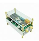
What surprised me is how small it is! If someone wanted to make up some appropriate brackets, this could be fastened to the back of a rig like the X108G or the Yaesu FT817/818. I think the Elecrafts are arranged the other way around - so that could be more of a challenge. The LPF board that I have is actually the same width but longer than the amplifier, that’s how small it is, with it’s fan cooled heatsink. I suspect it may well get quite warm if used for some time on SSB or on a data mode, purely because of its small size. I have yet to decide if I will build it into a pre-cast aluminium box that I have or leave it more open. The first thing is to wire it into the LPF board and apply power to both the amplifier and the LPF board and see how it all runs.
Thank you for the detailed information Ed.
I will be interested to hear how you get on with the 100w module for SOTA activation’s.
I run both the HF packer and MX50 at around 25w, current draw is around 6A on the MX, and a little less on the packer using a crude in line A meter.
I am trying to up my CW speed for the coming months, hopefully the barefoot KX2 will be enough if I can get proficient again.
Thanks again for all the responses.
73
Tim
G4YTD
Note that the intermod is specified at -120dBc at 28v it is much worse at lower voltages on that type of device, they are often used with a 48v supply (similar to the early Packer Amp using it’s FETs at 24v via an internal voltage doubler). It’s also designed for use around 900MHz the specs are probably much worse at HF.
I had a look at the spec sheet and there aren’t any figures included for lower voltage or lower frequency, just 28V at 960MHz. It’ll need a good heatsink running at 100W
AFAIK all the Packer amps did and still do use a switching boost regulator to provide about 30V HT for the output FETs so should have considerable resilience against low supply voltage.
Bearing in mind that the IRF510s it uses were designed for DC switching applications it’s miraculous what you can do with them!