Just getting things set up to take the 857 out on the hill. I already have a 6500mAh 4s LiPo, so a voltage dropper it is.
There’s plenty of posts describing what I need to do, but what I’m wondering is wondering why? Specifically, why do we tie the two AC tags together? It seems to me like it would work both with or without the strap. I’m sure Mr. Kirchoff will be along shortly to enlighten me…
Yes, this was my thinking, by strapping the middle you get two set of two parallel diodes connected in series. Perhaps this is seen as a more “balanced” approach? But (as far as I can tell) given that the 4 diodes have very similar characteristics, the current flowing through each one would be roughly equal in both cases. It’s just that without a strap the current splits and recombines, but with a strap the current splits, recombines, splits, recombines.
If I had built it out of discrete diodes I would never have thought of strapping the mid point. It’s only that I skimmed a few posts on here that even made me think of doing it!
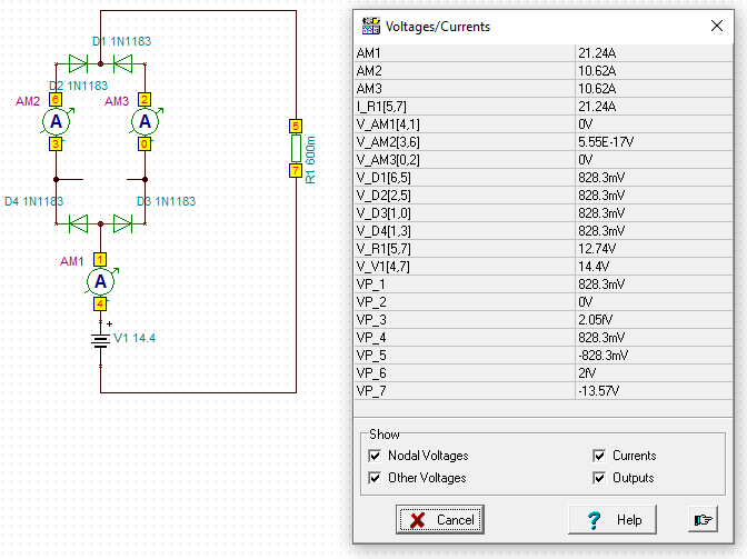
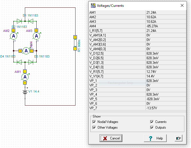
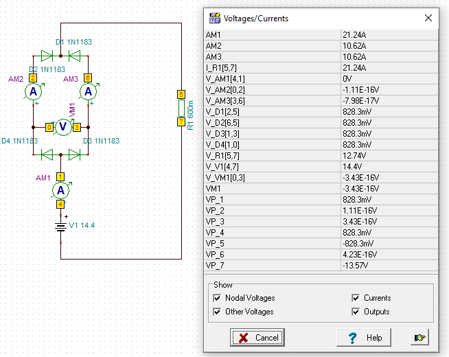
I don’t really like unsolved mysteries, so I thought I’d plug it into TINA to see what we get. The diodes are nominal - just what the software gave me by default. The short (in the form of the ammeter across the bridge) seems to carry nothing (a few femtoamps). Removing the short and putting a voltmeter across the gap yields a PD of similar magnitude.
I think in normal operation the bridge with the short is functionally the same as without the short. I can’t think of a failure mode for which the short acts as some sort of insurance. I wonder if it is simply something one person did because that’s their perception of how to crack this particular nut, and other people replicated because it worked.
I wonder if anyone has tried it without the short and how they got on?
Battery +ve to bridge -ve, bridge AC unconnected, bridge +ve to radio +ve.
This gives 2 diodes in series in parallel with 2 diodes in series. Voltage drop about 1.8V. As it is a bridge, the 4 diodes should be closely matched and the current in each arm should be very similar.
When the voltage on the LiPO starts to drop, short both AC connections to the bridge -ve. The first two diodes are shorted out leaving 2 diodes sharing the current and the drop is 0.9V.
Finally when the voltage on the LiPO is low enough, short bridge -ve to bridge +ve to remove bridge.
The advatage of a bridge is it is easy to mount on a heatsink, 100W = 20A and 1.9V is c. 40W to dissipate, heatsink needed. And should a diode fail in one arm, you still have the other to do the job.
Your analysis may be less clear because the Vf for all diodes is identical and it will vary a little in reality.
When the voltage on the LiPO starts to drop, short both AC connections to the bridge -ve.
Thanks Andy
Perhaps that’s the crux of my head scratching. I’m very much a “everything should be made as simple as possible, but not simpler” kind of guy. In other threads Brian @G8ADD reckons that an 857 is good down to about 10 Volts (others disagree), while Frank @G3RMD inserts his dropper for the first activation of the day and removes it for the rest, having taken the “top” off the charge. My plan was to start off with the dropper in line, and take it out one the voltage displayed on the 857 has gone down a couple of volts. It is mechanically simple and visually it is obviously either “in line” or “not in line”, somewhat reducing (but not altogether eliminating) the chances of me frying the radio.
With the short across the two AC legs, you have a nice common point to tie your switch to, the other end of which goes to Vin, for shorting out half of the dropper as you describe. Because I’m not putting in the switch, perhaps the short has become somewhat of a red herring.
Heat sinking is a whole other can of worms. I don’t really intend to go above 20W so I thought I might just get away with it. I realise this is probably stupid. I’m off to shop for heat sinks!
Thanks David, and yes, there is that option. Indeed, I do intend to try the 857 on my 5000mAh 3s and see how it goes. Looking through other threads it seems that some folk do just that and are quite happy with it.
All rigs will be different, but my example is happy down to 10.5V and I NEVER let the battery Volts go below 10.8V. I parallel two, 5Ah batteries and at 50W the battery last longer than the op. I usually find I have taken about 2,5AH from each battery.
I always use a battery monitor on my 3s batteries, so I could give it a go with my anticipated 20W without too much fear of doing harm. In fact, I’m already set up for that. I feel a trip up The Wrekin for the purposes of exercise, spending time outdoors, and self-training in radio communication coming on.
I use the same method with two graetz diode bridges or a couple of diodes found on a drawer.
Here a blog post where there are some of my considerations on his usage with ft-817.
Unfortunately in italian but you can translate it with G translator on the right.
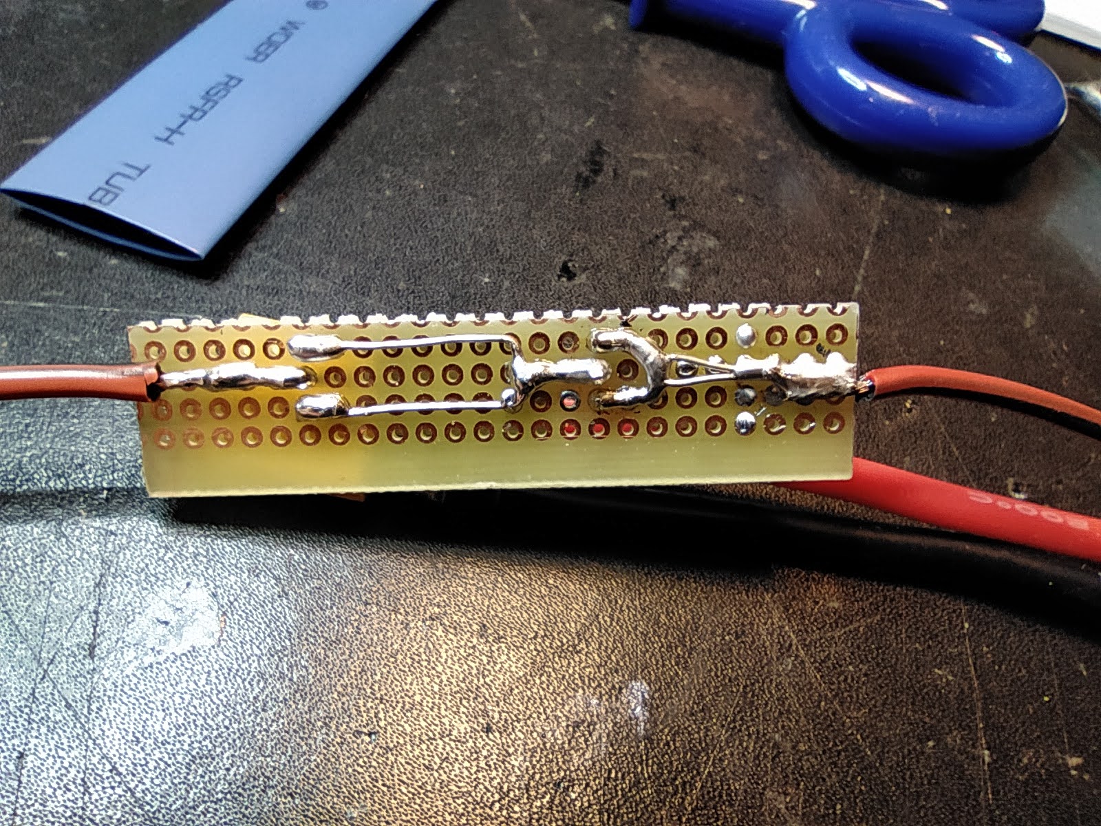
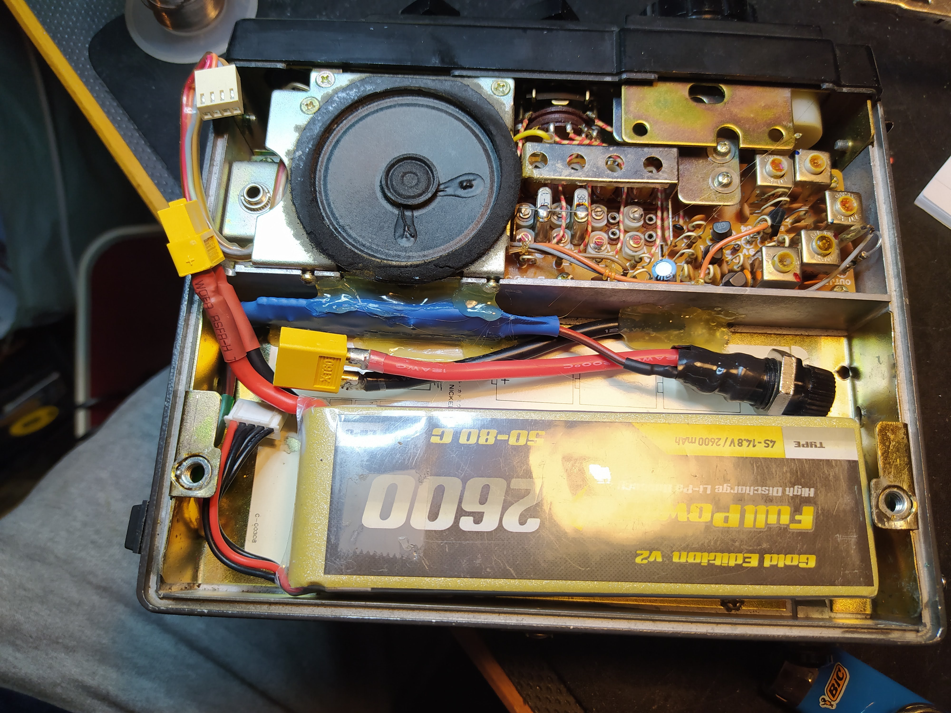
Below some photos on how I implemented it inside an icom 202.
In my opinion it’s necessary a sort of balancing between the two diodes in parallel.
This because they are not identical, so probably on will dissipate more than the other.
This could be solved with a power resistor in series with each diode.
But at the moment I’ve not applied this improvement.
An advise: use r/c model acoustic monitor to avoid lipo undervoltage.
Thank you Paolo. I think you are right. Having gone away and let it rattle around in my brain a bit, I’ve reached the same conclusion. As Andy @MM0FMF correctly point out, my analysis is based on ideal components. Bridges can be a bit “tippy” - e.g. the beautifully elegant Wheatstone bridge. By strapping the middle it ceases to be a bridge and becomes just a series parallel combo of diodes, and thus less “tippy”. (I assure you that this is correct engineering parlance).
I like your modern power source in a fine old radio! Its good to keep these things on the air. I am the proud owner of two Yaesu FT-290 Mk1’s (one of them thanks to the generosity of Matt @G8XYJ). I really should use them more, but mostly I just stare at them with love and misty-eyed nostalgia