Interesting !!!
5 Likes
Blinky works great and is easy to build.
1 Like
Interesting gadget.
If I understand properly, there is any firmware required in this one, right?
73 Iggy
1 Like
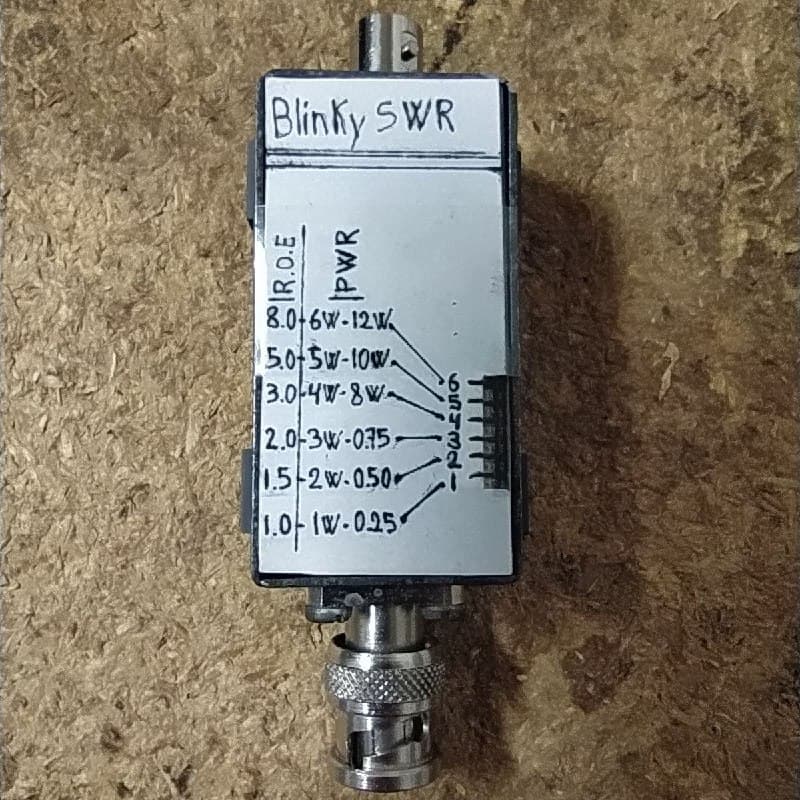
Yes, it’s a little microprocessor that is powered up by energy harvested from rectified RF. The microprocessor calculates the VSWR and RF power level, and then displays the results via LEDs.
73, Colin
Thanks for the hint
This is really very interesting… especially when operating with simple qrp devices.
I have also just placed an order.
73 Armin
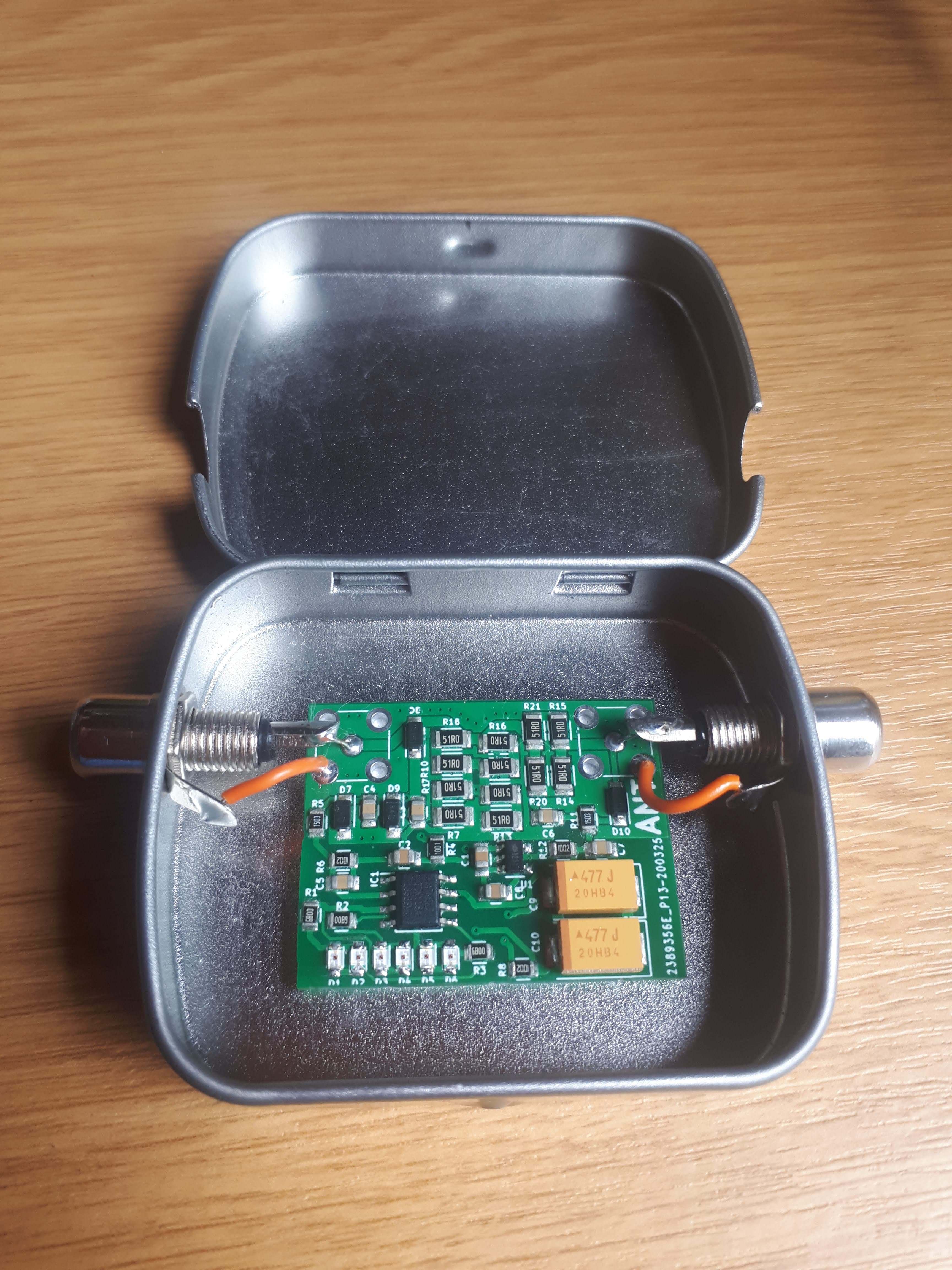
I finished my build of a Blinky SWR, and posted some history, a description and a few pictures on my blog:
73,
Luc ON7DQ
6 Likes
5 Likes
@DL6GCA
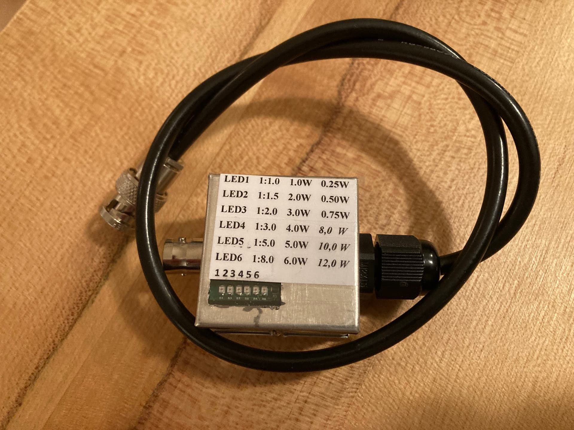
Good idea about the label Armin … I should steal, ehm … copy it for my box 
73
Luc ON7DQ
2 Likes
Hi,
FYI: Back in 2019, Vojtech pointed me to the potential problem that both his BlinkSWR and my TinySWR designs may add harmonics to the output signal. This is because the power taken from the RF signal clips the peak of the input signal, which produces harmonic content. If the clipping is symmetric, those are only odd harmonics (3th, 5th, …). If not, it may be even and odd harmonics.
I know that Vojtech took extra steps in his design to mitigate the problem, but it cannot be eliminated completely.
Now, I finally found the time to analyze this with the TinySWR and added a short section on this to the TinySWR Web site.
In my measurements, I found that
- with a Mountain Topper at 5W, all harmonics remain at least 50 dB down from the fundamental, so ok.
However, - the clipping increased the power level of the 3rd harmonic in my measurements by ca. 5…6 dB. (When computing the actual effect of the clipping, one has to convert the actual power levels with and without clipping from dBm to mW, obtain the power added by the clipping in mW by subtracting the power level of the 3rd harmonic, and then compute the relative power level of the additional harmonic content relative to the fundamental, if I get it properly.) So one cannot say “the clipping adds 5 dB”, because it is not amplifying from the existing harmonic content but instead *producing additional * harmonic content from the fundamental.
This should normally not be a problem, as the 3rd is typically more than 60 dB down. But if your output filtering is only borderline and the unwanted harmonic content is already substantial, you may have an issue.
When it doubt, better check the level of harmonic content.
One should also keep in mind that such an external SWR meter is typically added AFTER the low pass filters, so the added harmonics are not attenuated.
In the case of the TinySWR circuit, the largest source seems to be the RF indicator LED, so disabling that or experimenting with some RC filtering may help.
73 de Martin, DK3IT
PS: In the course of this analysis, I learned that rock guitarists use exactly the same phenomenon of diode-clipping an AC signal to add harmonics for a distorted sound ;-).
2 Likes
Hi Martin,
Thanks for reminding us.
The problem may exist with the TinySWR, since you can let it in circuit while transmitting.
But the Blinky (and other resistive bridge circuits like the earlier Rainbow tuner, N7VE single LED SWR indicator, etc) will normally be bypassed with a switch, unless one wishes to use the extra 6 dB loss for some QRPp activitiy.
I think it also depends on the load after the diode(s) : trying to recharge your battery from rectified RF will surely generate more harmonics than driving a moving coil meter or small LED (but you may have invented a perpetuum mobile, hi).
Makes me think … on a summit with a lot of transmitting towers … couldn’t we harvest some of that energy to power our QRP activations ?
73,
Luc ON7DQ
2 Likes
Thanks Luc, you are right! In the BlinkSWR case, this problem exists only during tuning.
Frankly, I was surprised by the magnitude of the impact of a bit of clipping when looking into it. And there are also many circuit descriptions on the WWW that will add even more clipping, e.g. the tuning indicator proposed by PD7MAA:

This will quite surely add strong 3rd harmonics, because the LED is designed to light up brightly during transmission, and clips directly at the antenna feedpoint. The capacitors might soften the clipping a bit, but the circuit is also not perfectly symmetric, so even order harmonics may also be added.
2 Likes
At 7MHz the 10pF cap will have a reactance of ~2K so will the clipping make much difference in a 50 ohm circuit?
1 Like
Hard to tell, but 2k means that 2.4% of the current of the output at now ca. 48 Ohms run through the non-linear circuit. For 5 W at 50 Ohms (well, then ca. 48 Ohms ;-), that is roughly 7.5 mA (rms) (of 316 mA rms - approximately). The exact level of the harmonics will depend on many factors, but I would not rely on being 43 dB down from the fundamental.
Also note that he suggests using this circuit at the output of the Z-match tuner, so the impedance at that point will not be 50 Ohms, could be much more (e.g. for a random wire antenna). But also much less, of course.
1 Like