I have the ATU-100 tuner, extended board, firmware version 3.0.
Does anyone know where I find the “RB1” contact on the board in order to extend / solder the push button switch there to activate the auto-function?
I am looking for the physical location of the RB1 contact on the actual board, I know where to find it on the schematic.
But I have seen other layouts with them on the backside of the pcb.
Maybe follow the trace from the PIC using the continuity function of a multimeter. 2 solderpoint on the back have the signals.
If it is the original design it looks like they are not populated at all:
@OE1SQA
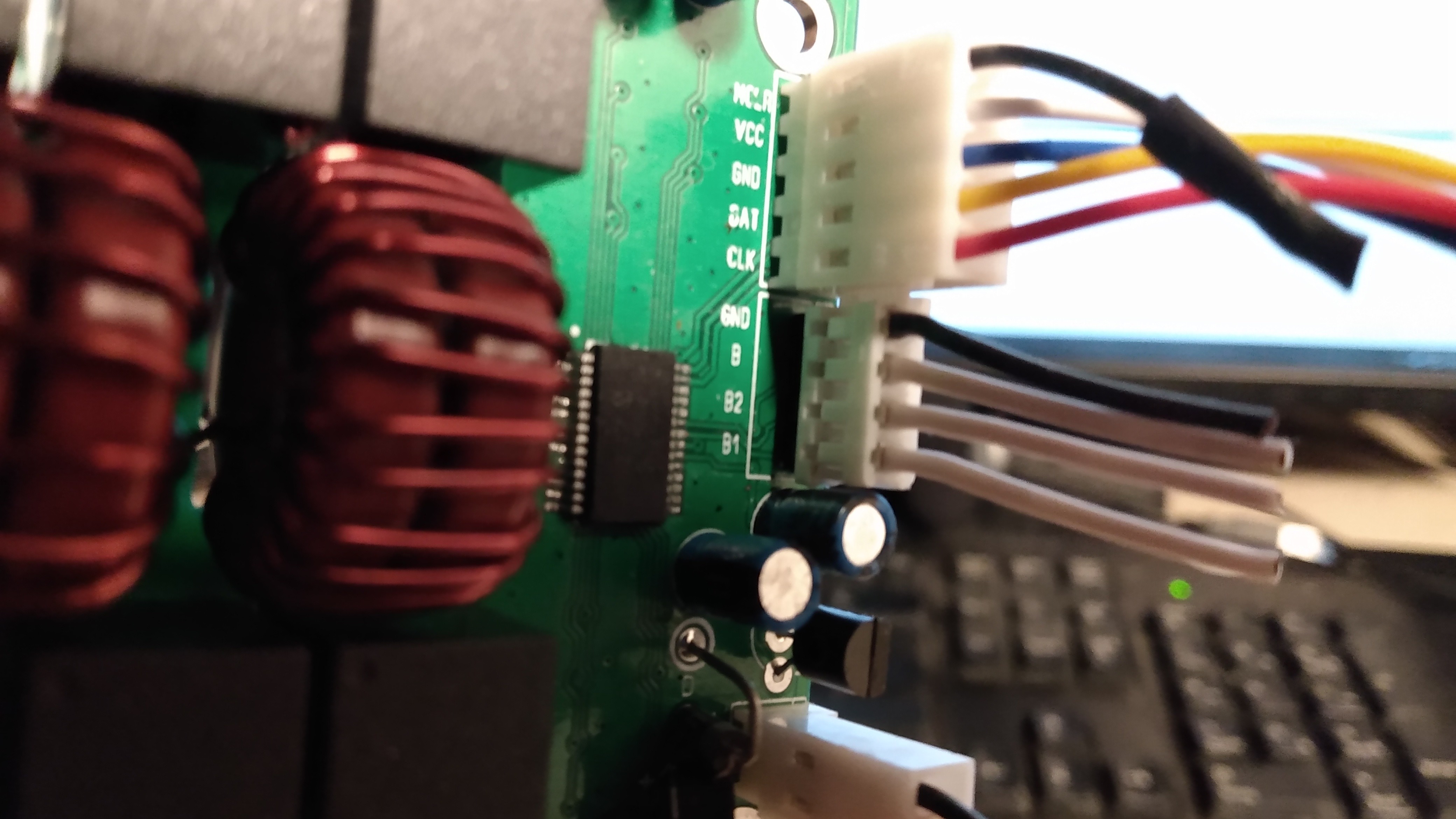
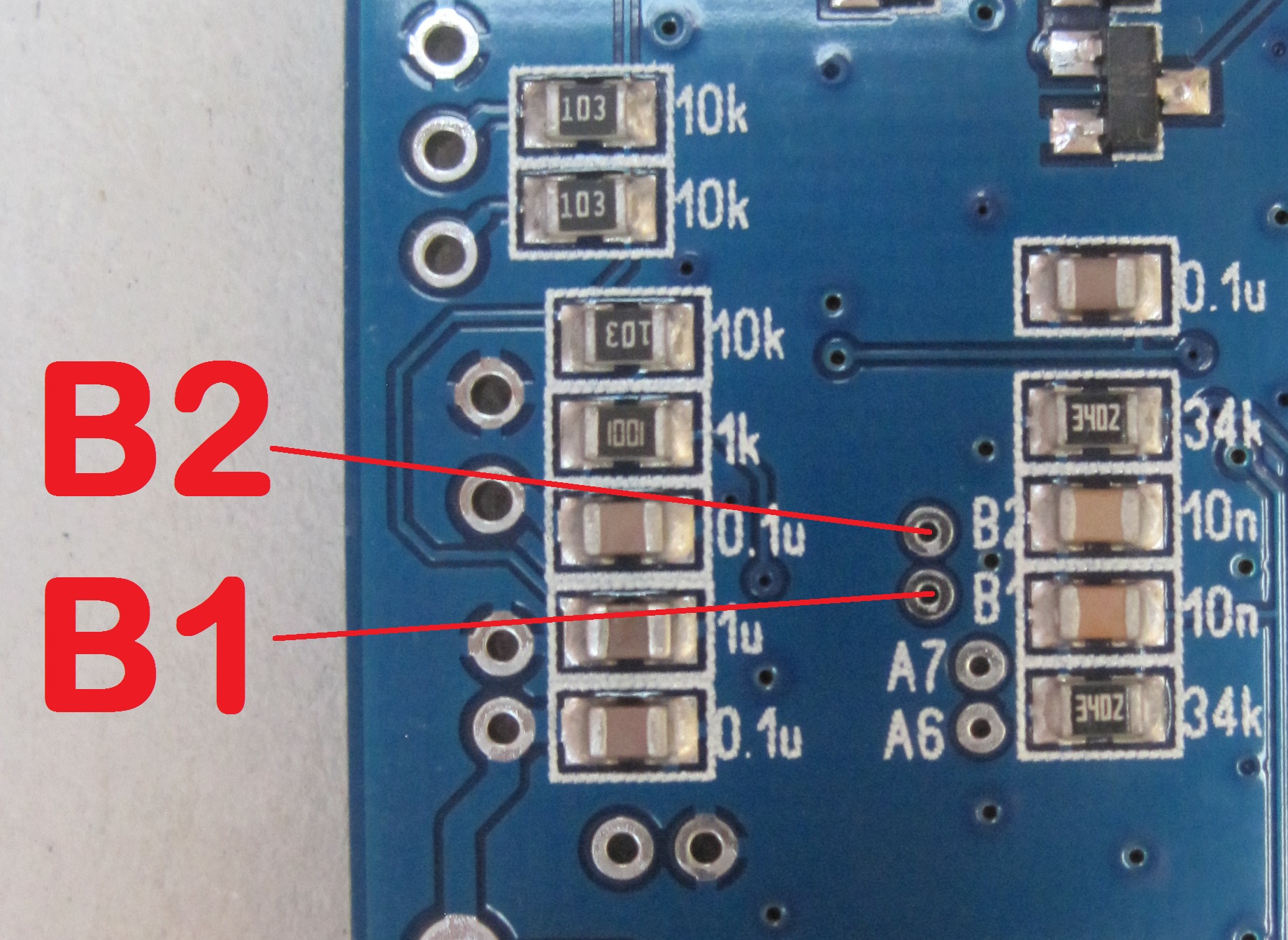
In my kit (Chinese version), it’s on the underside of the board, where the PIC is located, and marked as in the picture below, maybe a bit difficult to read.
I found it and I was able to solder the push-button. Mine is a chinese version incl. case and the RB1 and RB2 are on the backside. Some things were glued with some silikon like glue therefore taking it apart was also not easy just like soldering as expected since my tools are too large for this small SMD stuff.
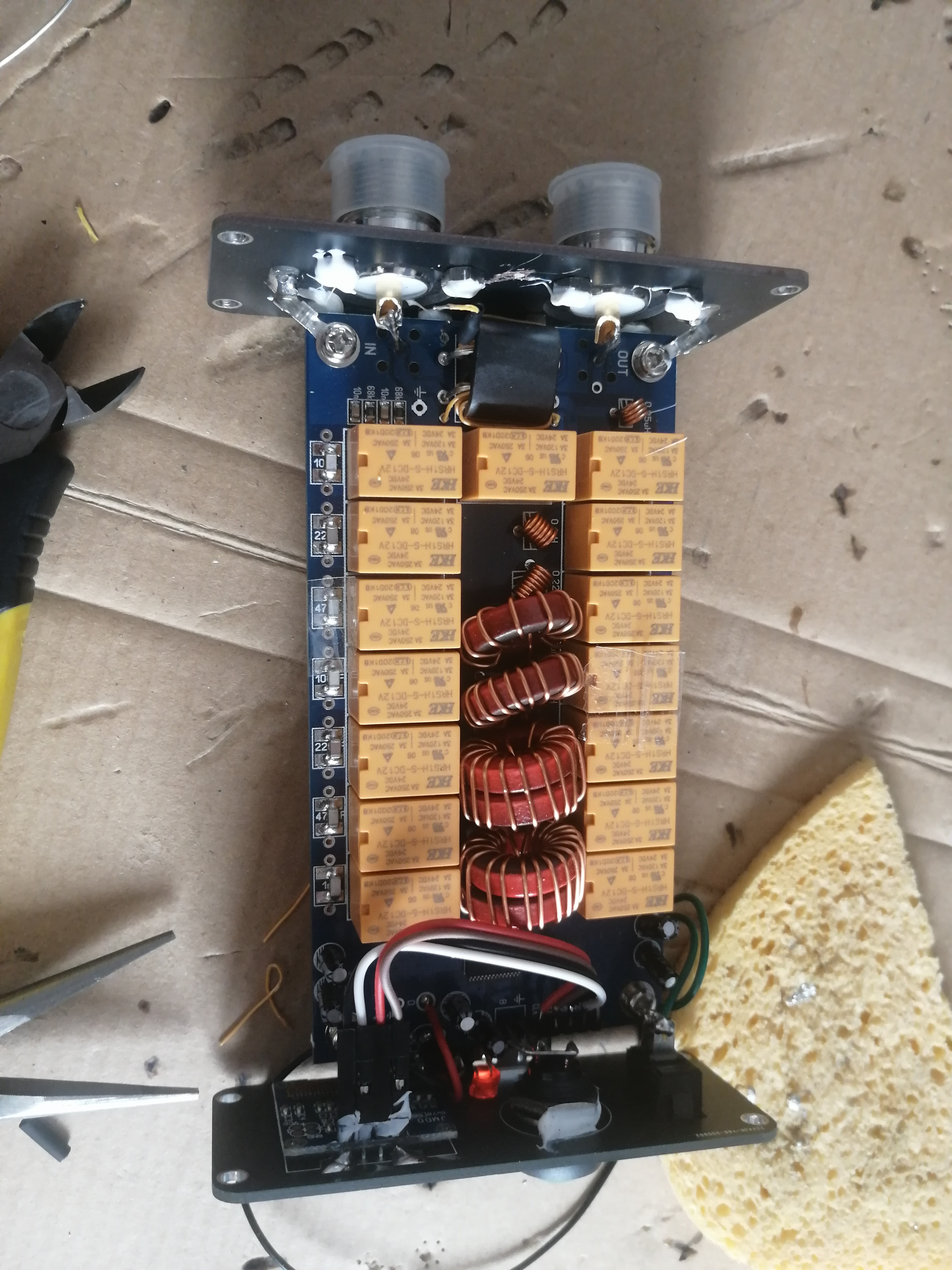
Since I was already on it, what I also did, was the modification to enable it for QRP usage (mine wouldn’t tune the FT817 for instance, power is too low.) I followed this instruction:
I have to test it yet though, removing 5 turns from the tandem match was also a mess with my far too large tools.
")