Arrow Yagi, with light fiberglass boom

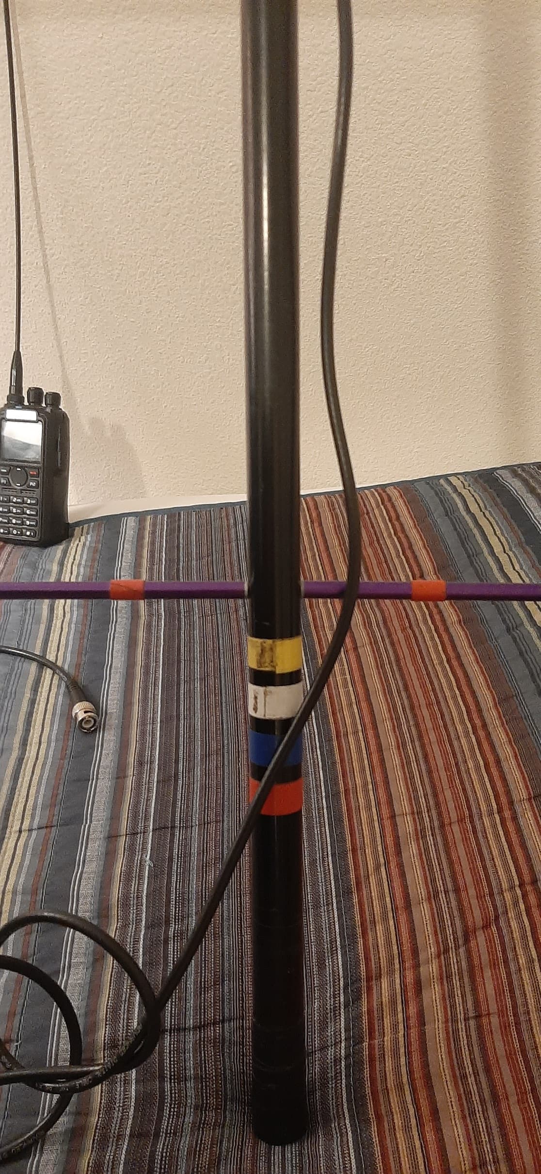
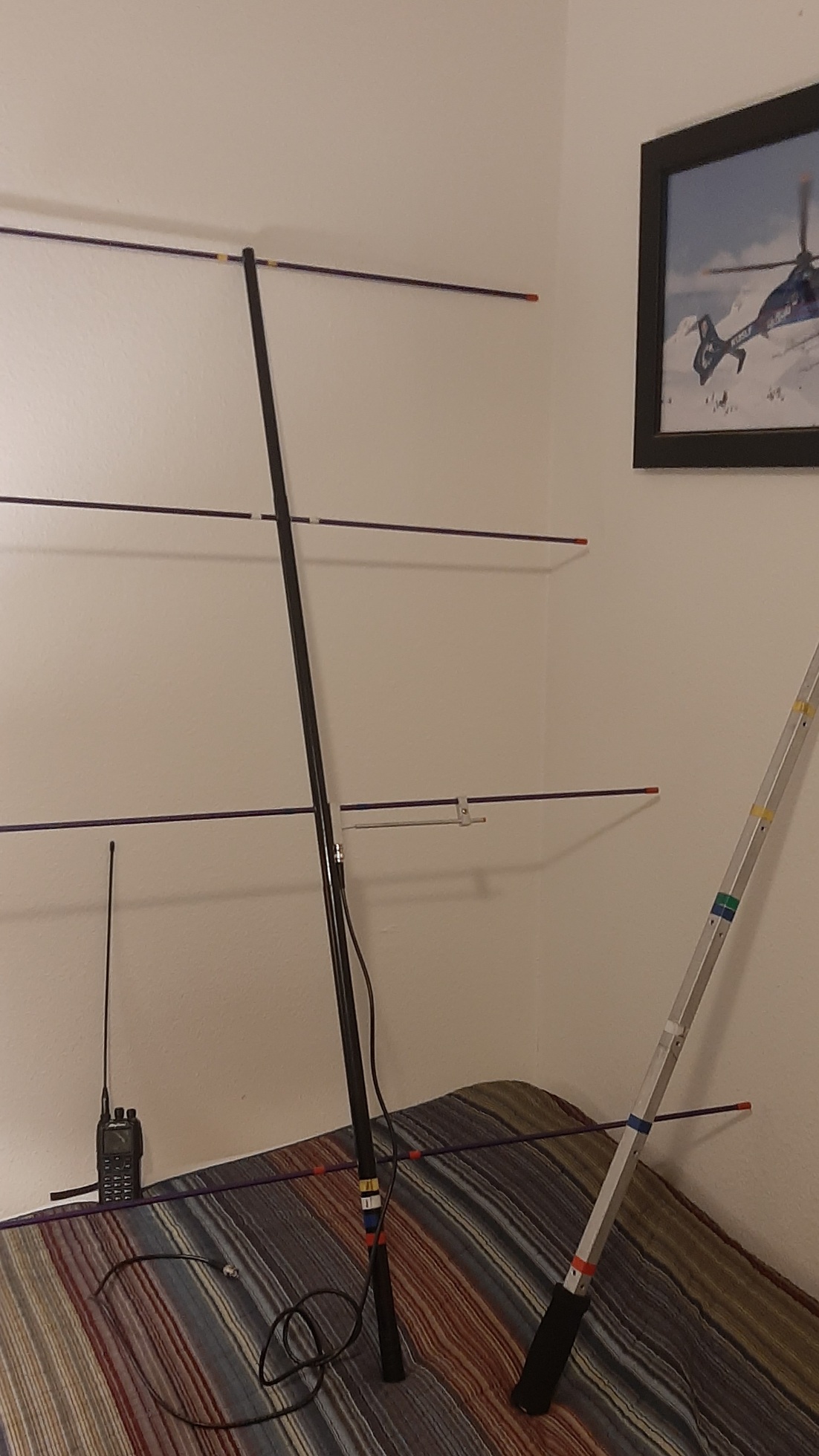
After talking to Tim, KG7EGT, about our antennas, I wanted to do some testing. I have an Arrow 3 element yagi, but to save weight I tried replacing the square metal boom with a telescopic fiberglass (fishing pole blank). I added a fourth element (actually, I bought just the four element set from Arrow, so I would have a second Yagi, one for me and one for my wife). It seems to work well, and I haven’t noticed a difference between the stock boom and my fiberglass one. Nor have a noticed much difference between using 3 and 4 elements. Tim said that the antenna might not perform as designed without the metal/conductive boom. I had wondered about this too, and I wondered if my modification was having a negative impact on my signal, but without me knowing it. So today I tried a bit of a test.

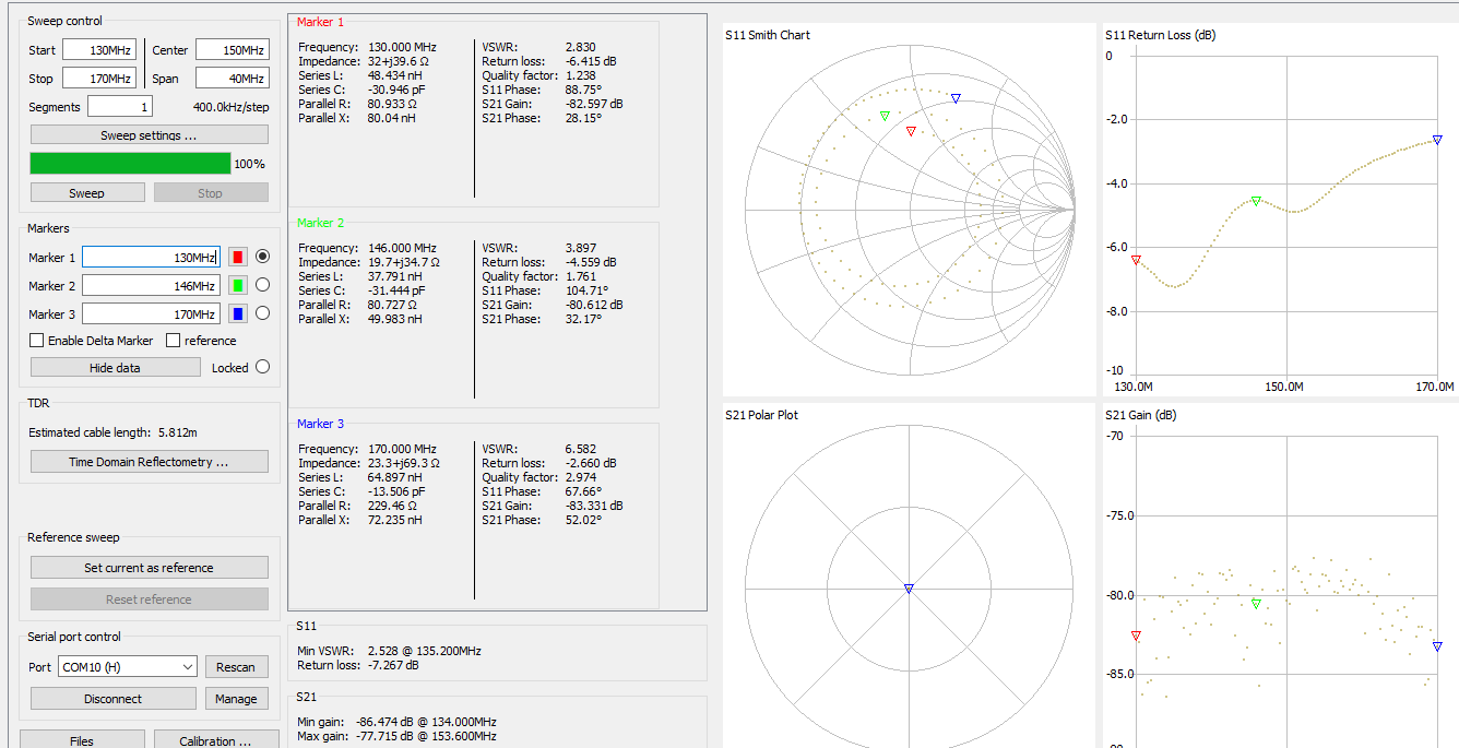
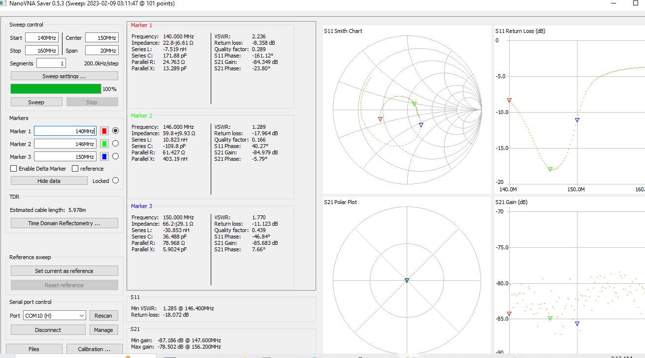
First, I checked the SWR with my Nano VNA. Here are the results on 146.5ish, with a 6 foot coax. I calibrated the Nano VNA, but I don’t know how accurate it is, as I was surprised at the SWR reading for the stock product. Moving the coax so it was perpendicular to the boom actually made the reading slightly worse.

Stock 3 element Arrow product 2.5 to 2.9
3 elements on my fiberglass boom 1.7 to 1.9
4 elements on my fiberglass boom 1.2 to 1.4

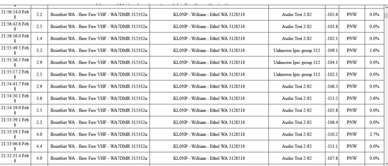
Then I tried the audio test talk group on the Bawfaw PNW DMR repeater, 146.5
I repeated transmissions x3 in each configuration, plus with a rubber duck antenna on my Anytone 878 radio, on high power. I couldn’t get the repeater with medium or low power.
With the rubber duck, I got an RSSI (dBm) of -116 to -113
With the stock Arrow boom, 3 element, RSSI of -109 to -107
With the fiberglass boom, 3 element, RSSI of -108 to -111
With the fiberglass boom, 4 element, RSSI of -106 to -104

I then tried again, 3 transmissions each, starting with 4 elements, then 3, then 2, then 1 element. (see last picture). I didn’t notice much difference, so perhaps it isn’t a useful test? The screen shot shows 3-4 transmissions per try, as I occasionally was turning some to look at the computer screen and lost connection with the repeater. I think that explains the outlier data points with the higher loss

My location was the Kelso, WA airport.


2 Likes

Now I like this idea a lot. I know other folk have drilled lots of holes in the standard booms. For some stupid, macho reason I bought the four element but it is really too heavy to hand hold in stock for (which to be fair they do say get the 3 element!)

This is a great alternative.

Thanks for sharing, Mark.

Hi Will,

Interesting experiment. The arrow antennas with the square boom are an example of a yagi with non-insulated elements, ie. the elements are not insulated from the boom as they pass through it, though the bit that goes through is just the 5/32” threaded rod. But the elements butt up against the boom and so the centre of each element is actually a section of the boom.

So when taking away the Al boom and replacing it with a nonconducting boom, the question is whether you mounted the elements on the fibreglass boom using the same threaded rod. The boom looks in your photos to be somewhat larger than the original boom (about half an inch IIRC). So that would mean the elements are somewhat longer than in the original antenna, which would detune them (to a lower frequency). On the other hand, this boom is nonconductive so the shortening effect of the original boom has also gone. So arguably the lengthened elements are close to what they would have been without the conductive boom in the centre of each element.

Your SWR measurements indicate that the SWR did change, so at least on the driven element, the impedance has changed. Without sweeping the antenna impedance over a frequency range of say 140-150 mhz, we don’t know where it is now resonant. I suspect this is partly what Tim meant by “it might not perform as designed without the metal/conductive boom”.

Clearly your experiment has opened up many questions and more experiments and measurements are required.

The EME antenna builders have devised a formula for calculating the shortening effect of a conductive boom. It is a significant change. A lot of the work on this was done by Guy Fletcher VK2KU (SK), who was a good friend.

I look forward to seeing more results from your experiments.

73 Andrew VK1DA/VK2DA

2 Likes

I will never get why people buy a VNA to use it as an SWR meter, instead of measuring reactance, which would clearly show on which frequency the antenna is resonant.

Ahoi
Pom

2 Likes

The fiberglass boom is almost the same diameter as the thickness of the square stock boom. Pretty much exactly in the center, but it does taper slightly. So the element lengths are very close, as I can tighten them more on the thick end, compressing the fiberglass, and leave them looser on the narrower end. They are connected through the fiberglass boom using the same threaded rod.

I also tried to sort of simulate having a conductive boom by hooking a thin wire on the end of the fiberglass boom, and wrapping it once around each element where it crossed the boom. Not a very good electrical connection, probably. But it did raise the SWR to about 2.9 from 1.4 without the wire.

I guessed the non-conductive boom does have an impact, but I wasn’t sure how to check if it mattered enough to justify carrying the extra weight. I am new to playing with the NanoVNA, so aside from calibrating it using instructions on YouTube, I may not even be using it effectively–other than the fact that something does change with the non-conductive boom. Of course, after carrying it on many summits, I wonder if any corrosion or physical damage to the gamma match or anything else is impacting the results. I tried cleaning all the metal parts that touch with a wire brush and WD-40.

I then repeated the sweeps with the Nano VNA and took screen shots.
The first one is the stock, 3 element, with metal boom

Then next is the 3 element with fiberglass boom

The last is the 4 element with fiberglass boom

The other thing that just occurred to me is that the elements are from a four element yagi. I assumed that a four element Arrow Yagi is the same as a three element, but just with one more element. I didn’t consider that the driven element might be tuned differently for a 3 element than a 4 element Yagi. I have another 3 element Arrow Yagi at home, I will have to compare the two when I get off work. Yes, I am allowed to do these experiments while at work :slight_smile:

If anyone has suggestions for helping me either interpret the results, or run more effective tests, then I am happy for advice. That is why I figured I would post here–I don’t really know what I am doing! And it would be nice to know if I am missing potential contacts due to an underperforming, modified antenna. Thank you

1 Like

The figures of four elements on glass fibre boom look acceptable, however X=9.93 Ohms @ 146 MHz is too high and could be improved.

What I would do is, check what’s wrong with the measurements (coax cable too long, out of spec, bad connectors?) and then check the gamma match. I can’t believe that a professionally desgined antenna has almost X=34.7 Ohms at its specified frequency. In a 50 Ohms system, this means 70 % loss.

Ahoi
Pom

1 Like

yes, that is why I was wondering if hundreds of miles of abuse in my backpack have had a negative impact on the match or the coax or something. I will have to compare it to my other, 3 element, Arrow yagi.

Or it could be that I am doing something wrong with the VNA, as I seem to be getting great results in the actual use of both the stock antenna and my modified version.

1 Like

I’m curious about a few things. Disclaimer: I have no direct experience with Yagi antennas.

  1. what is the environment around the antenna when you measured SWR? As an extreme case, leaning it against a car would majorly throw off results (not implying you did). I would not be surprised to see a fair amount of variation with how it is positioned relative to the ground but don’t have any measurements to back that up. I could be wrong.
  2. is the VNA calibrated to the end of the feed line or just to the output of the VNA? Of course you want to ultimately see a nice match at the radio end but it may help sort things out to start with calibrating to the antenna end of the feed line or even dialing in an electrical length offset and do a quick check at that point with and open/short/load to verify they look right.
  3. having never used one of these for SOTA, are you hand holding that or do you do something else to mount it? I almost exclusively use a roll up J-pole that I hang from a tree for 2m SOTA. But I also live somewhere where essentially all summits are tree covered.
1 Like

For the environment, I was outside, greater than 15 feet from any metal. Out of curiosity, I tried running some sweeps indoors, and it had a large impact, especially if I was near the 6-foot tall metal cabinets. I am holding it at arm’s length, so not too far off the ground. Turning from the usual vertical orientation to horizontal also makes a difference in the readings on the VNA.

I calibrated to the output of the VNA. I use 6 feet of RG 58 between the VNA and the antenna. I put a 50 ohm load at the antenna end of the coax, and it reads 49 ohms on the VNA. But I will have to try calibrating at the end of the coax.

I hold the end of the boom by hand, as many of my summits don’t have trees.

1 Like

Pointing a yagi vertically up can be useful for taking measurements, but you still need to keep it clear of your body etc.

Thanks for posting, I always like to follow such discussions, and often learn from them!

1 Like

By vertical, I mean the elements are up and down as commonly used for FM, not horizontal as a see people doing on SSB. But the boom is still horizontal. The Arrow antenna is designed with a hand grip on it, and I see pictures of other people using it hand held like that. I have tried mounted on a pole, but never seemed to gain enough benefit over the extra weight and time of dealing with a pole/mast. So I figured it would be good to test in the configuration that I am using it.

3 Likes