Antennas for DX: exploring about interesting wire antennas

Disclaimer:

Antennas is a very addictive subject. If you pass from this point on it’s under your responsibility.

Bear in mind you’ll need about 10 minutes for a proper reading of this post (so go and grab a beer before you get on with the reading…).

1. Motivation

As the solar cycle nr. 25 starts its ramp up, with a good solar flux developing since last months, I decided it was the right time to design and test an antenna focused on DX.

I usually run an inverted vee EFHW antenna with good results for SOTA activation with many Local and inter-EU contacts in the log.

Nevertheless, every now and then there are especial events where we focuse on working DX specifically, like for the EU-NA, or the EU-VK/ZL.

What would be a good antennna choice to have some gain and produce a low take off angle?

I would be very happy to have a 4 element yagi at hand up in a summit but that isn’t realistic. I will try to look for feasible options to build a light wire antenna that can be deployed in a solo portable expedition without becoming a hard stuff nor getting mad!

Let’s start planning.

2. Target and initial considerations

In order to compare the main features of some wire antennas I decided to run several simulation models in Mmana software.

We should be cautius with the resulting plots and figures, as we know that real performance of an antenna will depend on the actual soil conductivity characteristics, terrain slopes, near obstacles, etc, but the simulation would be an easy tool to have a qualitative comparison of the expected results and will identify differences between a range of several different models.

The basic targets to achieve with a good portable antenna for DX are:

  • To get some gain and directivity, focusing on a low elevation angle, improving the take off (TOA)
  • Bands of choice: 14 MHz and consider higher bands like 18, 21 MHz…
  • Consider a way to get a Multibanding antenna, and not too complex for a quick band change.
  • To provide a reasonable impedance, minimizing the use of tuners whenever possible.
  • To use a moderate height of the required masts to keep weight and portability.
  • To limit the number of required masts at two maximum, for ease of setup in a solo climb

To put some limits to my dreams, I fixed the height of required mast support to 10 meter maximum, and decided to limit myself to use up to two of these masts. Bands of choice will be 20, 17 and 15 meters.

3. CHAPTER A: REFERENCE ANTENNAS

From this point on we will see a number of characteristics for different antennas. To limit the information to a reasonable level, only the following features are shown:

Z: impedance (ohm)

Max Gain: expected maximum gain (dBi) indicating at what elevation angle

Gain 5, 10, 15, 20: Expected gain at 5, 10, 15 and 20 degree elevation angle

GainRef: Expected gain over a reference antenna. More on this later.

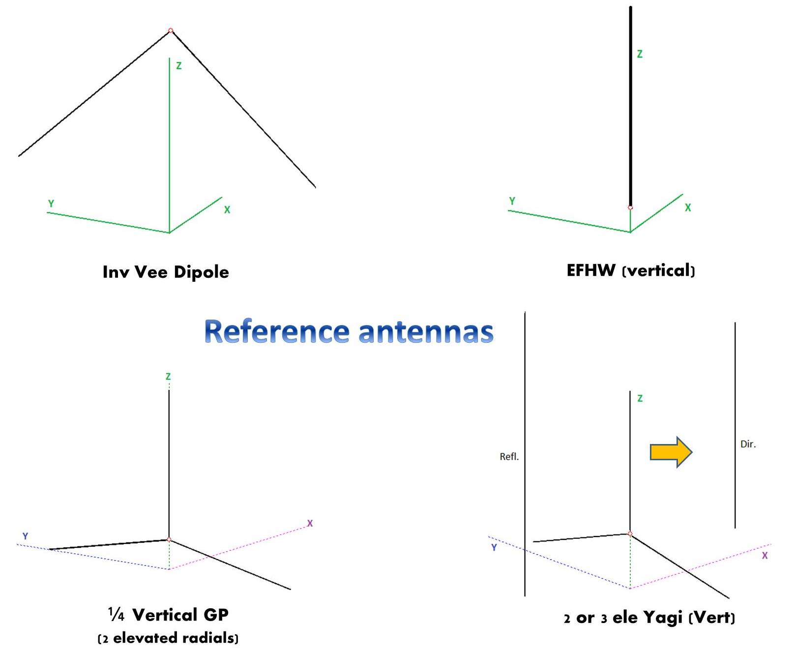
As a starter, I considered first some basic wire antennas to have a basis line.

They are common for a portable wire antenna; some are omnidirectional, not a beam, but I took them as a starting point.

3.1. Reference antenna: Dipole

That’s the first obvious choice. To achieve some gain and see the variation I simulated a 14 MHz dipole at two heights over ground: 6 and 10 meter.

3.2. Reference antenna: Quarter wave vertical with two elevated radial.

I know it could be better to add some radial for a pure omnidirectional pattern, but I decided to use just two for simplicity in the setup and because this feature is better for a later modification of this basic design.

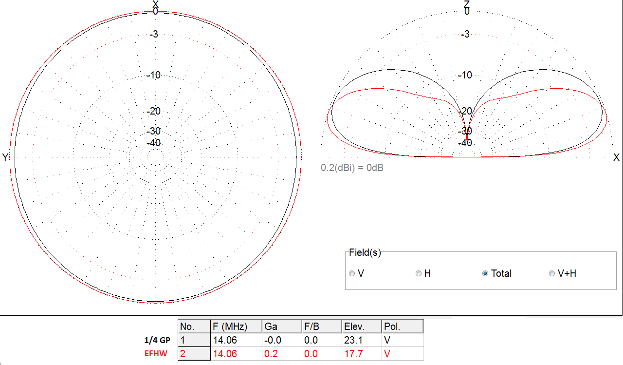
3.3. Reference antenna: End fed Half wave vertical (EFHW)

Instead of a inverted Vee or inverted L, I simulated it vertical to have the better TOA elevation angle. See the slight improvement when compared to the Quarter wave vertical:

3.4. 3 element vertical Yagi

This is not a common antenna, as you need 3 masts to setup the three elements for this antenna, so not an option for what I’m looking for, but I just wanted to see about gain difference when using a wire beam.

For ease of setup I used the basic Quarter wave vertical with two elevated radials as for the driven element.

See all 4 designs here:

And let’s see their performance now:

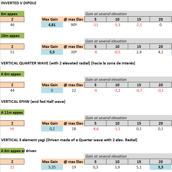
Right, we see that, except for the vertical yagi beam, all the basic antennas are omnidirectional and therefore you don’t get any gain at low elevation angles.
It’s time to look for better alternatives now.

4. CHAPTER B: WIRE ANTENNAS WITH GAIN (at low angles)

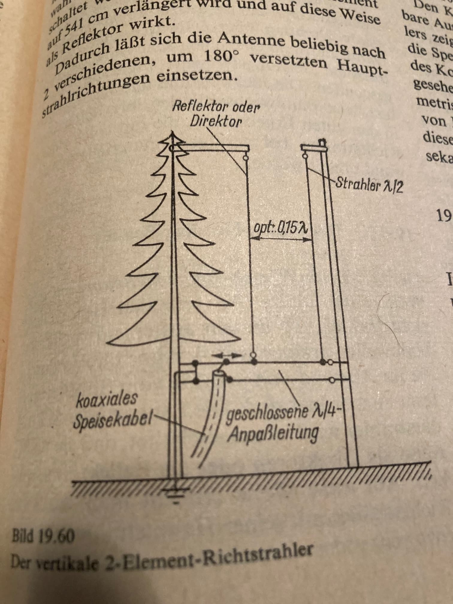
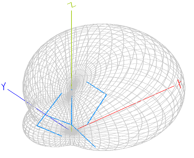
4.1 EA2BD’s HYBRID 3 ELEMENT VERTICAL YAGI

It’s obvious that I can not raise a horizontal polarization yagi on a tiny fishpole. In the other hand if I want gain the easiest way is to stick to Vertical pol.

Is there a way to design an easy-to-deploy Vertical yagi: Yes! After some reasoning I created this unique model with a single center support:
Hybrid 3 Yagi

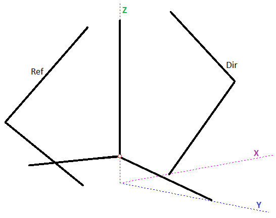
As you see, only a center pole is used and both the reflector and director are bent as a side Vee hld with the aid of rope at certain distance of the center mast.
You may guess that its performance is not as good as a true vertical yagi with straight elements and you are right, but despite the loss, the resulting beam is not bad:

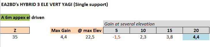
There is a 1 dB loss compared with the pure Yagi, but, you still get much more gain when compared to a Dipole or any of the vertical reference antennas (in example, about 3 dB gain compared to the EFHW).
Here the 3D pattern of my design:

And here the comparison between the “pure” and my “hybrid” model:

Performance of a yagi seems the right approach for a DX antenna, but…
I should decide in advance if I should orient the antenna to beam Short path or Long path, because I won’t be able to rotate a wire yagi once setup in the wild.
Therefore I explored some other wire designs (not mine) capable of a simultaneous beam towards opposite azimuth.
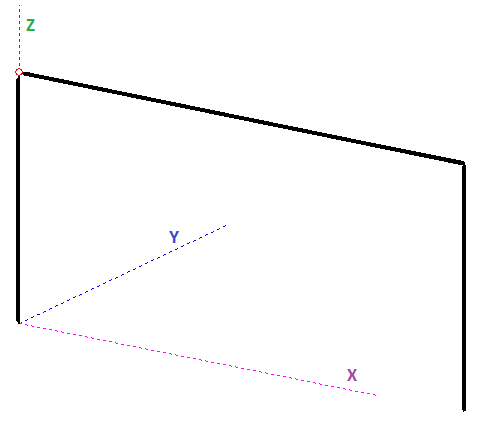
4.2. HALF SQUARE
This one is a good choice for portable. It is a vertical polarization antenna and requried height is not that big: Appex is still at 6 meters for 14 MHz. Feed point is one of the top corners, requiring a long coax running up.

HALF SQUARE

Performance:

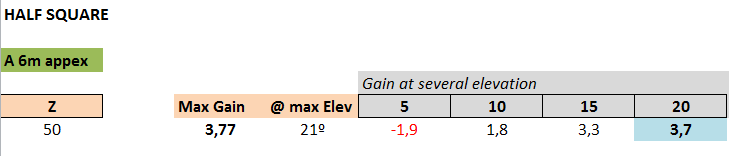
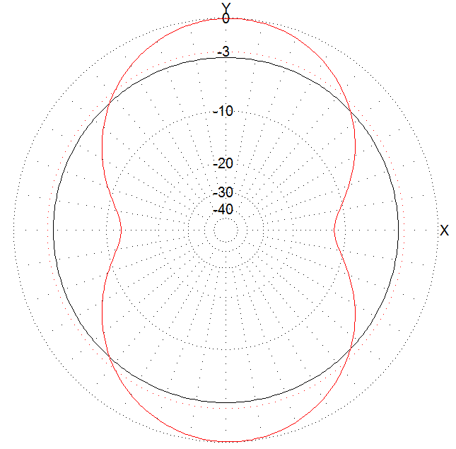
Pattern (in red) compared to a Vertical EFHW (3,6 dB gain @ 20º for the Half Square):

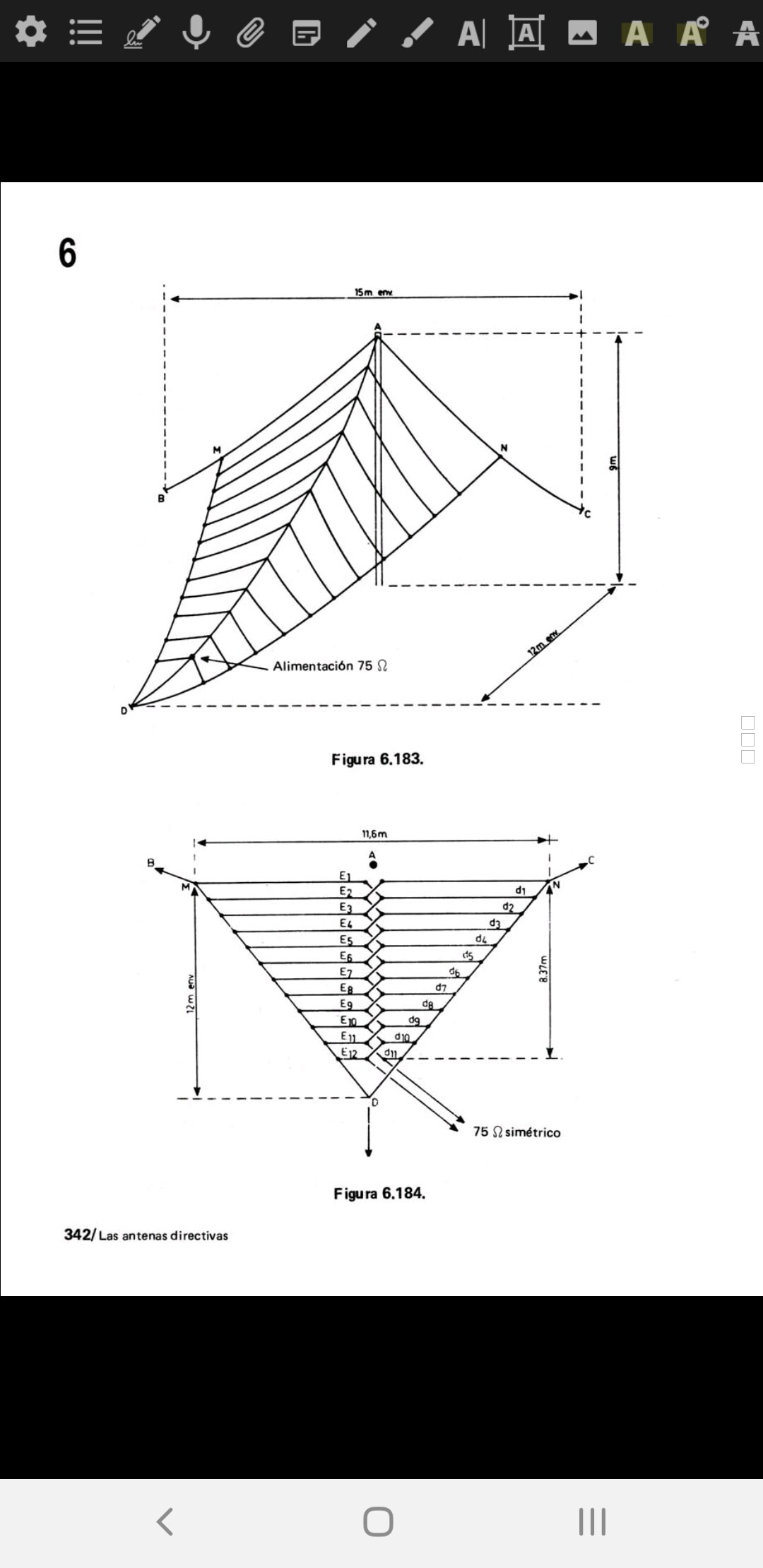
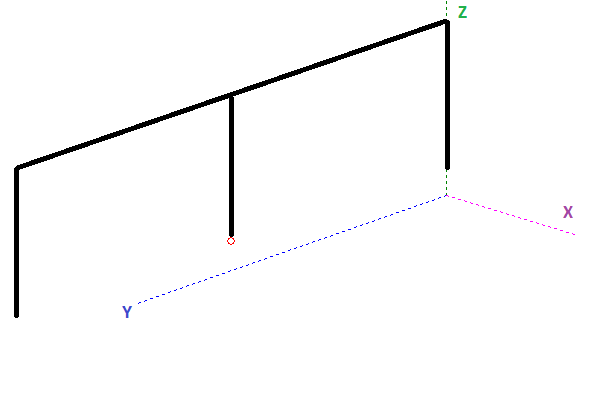
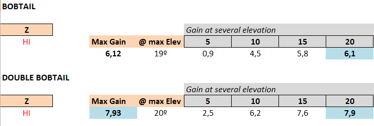
4.3. BOBTAIL & DOUBLE BOBTAIL
This one is an interesting antenna though it is very large. It is made with three 1/4 WL vertical radiators connected by two long horizontal 1/2 WL sections:

BOBTAIL
Its performance is higher gain compared to a Half Square, but this long antenna (20 m end to end) is not for every summit. Feed point is in the top middle vertical section, but could also be fed at the bottom middle where the impedance rises to a very high value requiring a impedance match (similar to an EFHW).

A nice variant is a Double Bobtail (thanks Adam @K6ARK for the idea, as shown in Youtube), composed for 2 parallel equal Bobtail antennas, 5 meters apart, so that it’s converted into a beam. If you want to reverse direction, simple choose which of the two Bobtails to fed.
See a comparison between the Single or Double model, this one has truly Gain!

Pattern comparison between the Single / Double versions:

Although you could enlarge one of the two Bobtails to get a higher gain, the idea to have both equal to be able to feed either antenna was nice to flip the beam easily.

Well, there is no doubt this monster antenna is intersting. The bad news is the complex setup that requires much more poles (4 minimum in the corners for the Double version) and space in a summit.

5. CHAPTER C: HOW CAN I GO MULTIBAND?

All the above models were an interesting exercise: I could qualitatively compare these designs without cutting a single piece of wire and comfortably seating in my living room…

They provided some promising figures and I could see what to expect from them, but I decided to research a bit more to design a novel antenna that was very easy to setup, didn’t require a huge space, that could be used in more than a single band, and that I could easily change the beam direction.

I focused on 14-18-21 MHz.

5.1. EA2BD’s CHEAP 2 ele BEAM
I tried to model this very simple 2 element vertical beam:

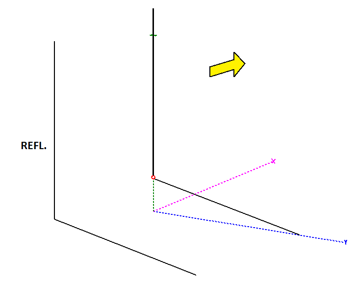
The Driven element is similar to a doublet dipole but installed as of a quarter wave with a single elevated radial (along the Y axis). Both wires are 5,2 m long. The feed point is a short parallel line that goes to a Z tuner (ZM-2 in example) so that it can be tuned in the three bands, 14-18-21 MHz.

Then the Reflector, spaced 5,5 m apart from the Driven, has a vertical wire but also has a quasi horizontal leg deployed along the Y axis, and parallel to the driven. This bottom leg is tunable, so that it can be shortened (manually bypassed) at some points to make it possible to act as a Reflector also for the other bands.

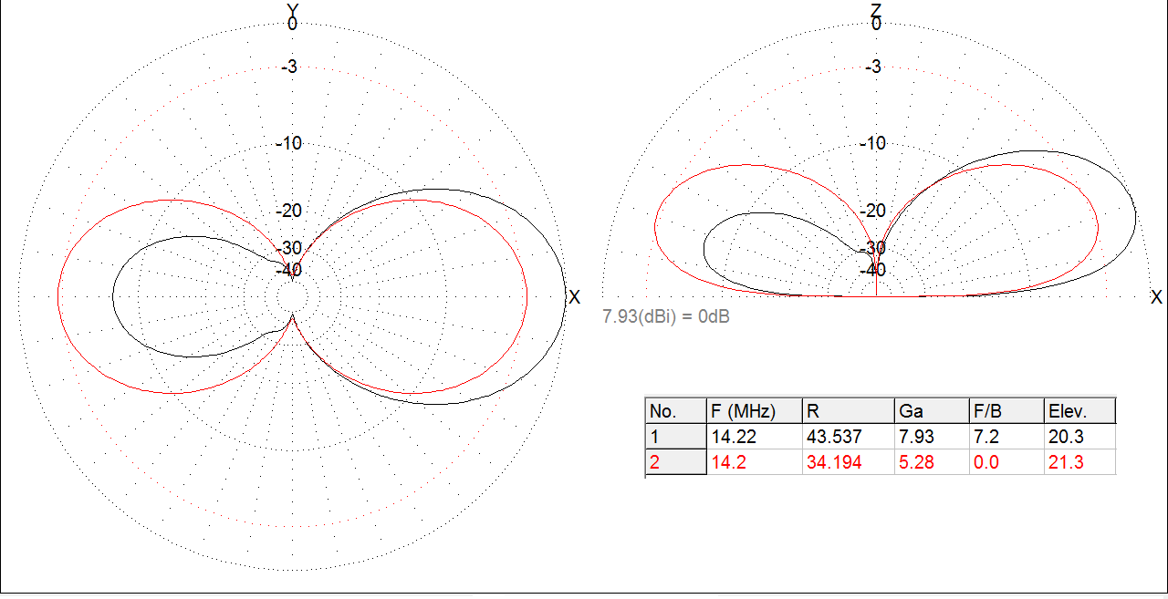
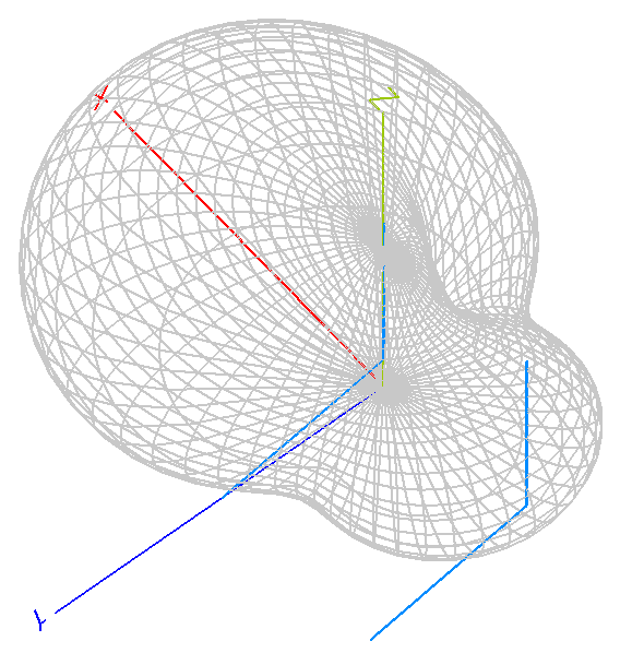
The beam looks promising in the simulation, see the pattern and performance for 14 MHz:

Such figures are similar to the ones obtained with the Half Square antenna.
Performance for 18 MHz or 21 MHz with an easy reduction of the Reflector length in the horizontal wire provided these values, also satisfactory and not far from the 14 MHz results:

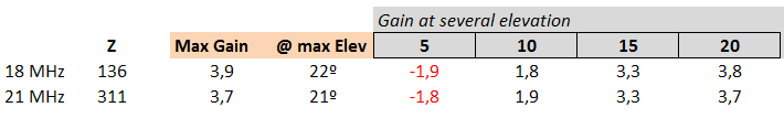
Converting the Reflector into a Director would be ideal in orther to flip the beam direction, but it resulted to be tricky, being only possible by reducing the vertical wire length and not the horizontal one, being therefore less practical in the field. In the other hand, the director wasn’t as efficient and produced a reduced gain.

6. Research on hold

There some other designs that I didn’t included here as they would require more experimentation (and time!), in example:

  • 2 element arrays (with a coaxial delay line plus switches to reverse the beam direction)

  • the VP2E wire beam

  • Others…

7. What’s next?

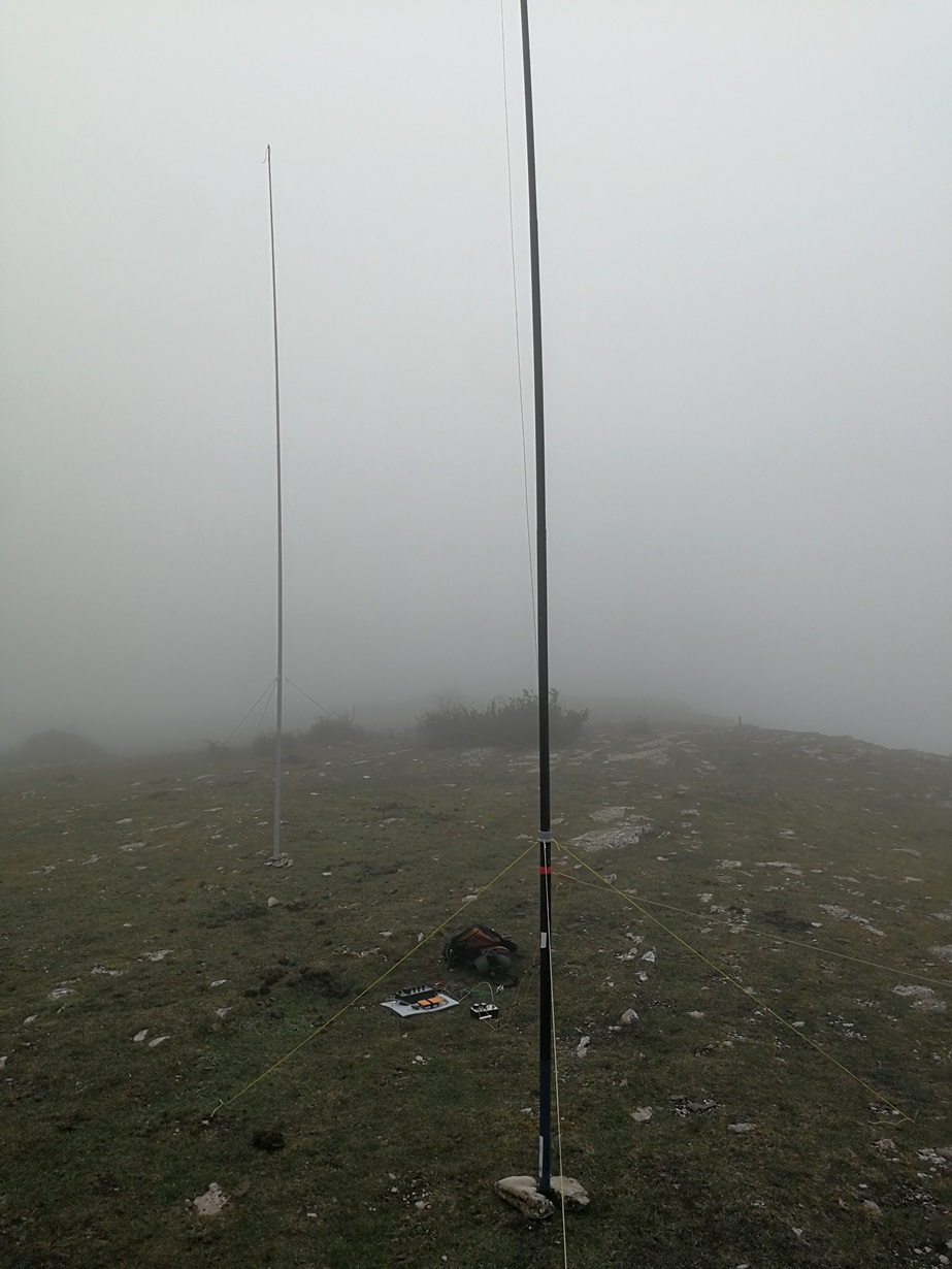
Simulation was a nice game to play and compare things, but, what about real life?

I should start cutting some wire now, perhaps to builld one of my "cheap and dirty” ideas. If I am lucky I should go out and try testing one of these wire toys. I promise to tell something soon.

Is there any good advice you could add here? Game is over. Thanks for reading.

73 de Ignacio

17 Likes

Relative field-strength measurements in situ.

Ken

2 Likes

Hi Ken,
you’re invited to come and measure around while I key down at the rig.

And have a beer afterwards meanwhile we comment on the results, hi.
73 Ignacio

2 Likes

Ignacio,

Height is your friend. The ground reflection tilts the main lobe up. Even a vertical and 4 elevated radials, unless it is high, it won’t give a really low take-off angle.

So how high? 10 wavelengths? Hard to get on 20 m with a backpack pole.

But if you can find a summit shaped like a sharp cone or one with a steep fall off in your desired direction then the standard 7 m pole will do. As the ground immediately in front of the antenna is not there it can’t reflect, or if it is at a steep angle the reflection is away from the antenna so it has a minimal effect on the pattern.

In such a location a simple dipole in inverted vee (one mast) or strung between two masts will give value for effort.

Operating at harmonic frequencies is OK if you have the lobes that form in the right direction.

A simple vertical with three elevated radials will give the best all round radiation pattern and if near a cliff edge etc will be great for dx.

The best bang for buck in gain antennas is the two element beam. For multi frequency operation the W8JK design, although 80 years old, is still worth considering. It works with two wire elements in inverted vee shape.

Personally I prefer simplicity. I have used a delta loop on 20 m in the hope of some dx. On a ridge or cone it will be about as good as it gets. You do need to get the bottom wire elevated and that’s a problem with a 7 m mast. A delta loop for 20 m can be opened out to become an inverted vee on 40 m.

All my SOTA dx, 16,000 to 18,000 km, has actually been worked on a linked dipole. The 3,000 km and less stuff is local down here.

73
Ron
VK3AFW

7 Likes

As I grow my understanding of amateur radio I’m coming to think it’s really amateur antenna. The radio is just latched on as a “proof of design” exercise :wink:

5 Likes

Thanks Ignacio for your effort in putting this information together. :+1:

Very interesting.

Regards Geoff vk3sq

2 Likes

I have come back to testing the VP2E (Vertically polarised 2 element antenna) which I built almost 2 years ago and looks like a double-sized inverted V OCF but electrically it is supposed to work as a driven element and a director.
I have built two of these antennas - one for 40m and one for 20m.

The other more “normal” directional antenna is my vertically polarised Moxon antenna that requires two masts, I have these built for 10m and 15m.

In both cases, I am at point 7 in your list - trying them out in the real world on summits.

I must point out however that currently from summits in Germany it’s possible to work DX - i.e. into VK & ZL even just using the simple linked dipole antenna if you are on the air at the correct time.

Here are my write-ups:

VP2E:

Vertical Moxon:

73 Ed.

2 Likes

I have to echo Ron’s words about operating on a slope/edge. Recently I’ve been repeat activating a summit if I don’t intend to drive or walk further (35min drive, 6km round trip walk and 280m ascent, a nice bit of exercise.) I have activated it many times normally right on the top but since working from the quite steep sloped side (to escape the wind) it’s quite noticeable how much better an Inv-V dipole is than on the flatter top. It fact it’s so noticeably better that it’s worth operating from such slopes if available. Sadly there are plenty of summits and plenty of less clement weather that it’s not always feasible in Scotland.

I’ve already revamped my 1/4wave GP for 12m (just made sure all joints etc. were in good condition.), made a new top radiator for that to swap it t0 10m and tested both when there was SpE last year. Also I made a 10m delta loop that works well. That means the higher HF bands are covered. I have dipoles for 80 (it’s enormous), 60/40/30/20/17. Since making 2 little extensions, the 40m dipole can be made into a 3/2wave dipole for 15m.

Looking at all antennas and the current state of the bands, I feel that the DX band for this year may well be 15m and it’s one I’m not well covered. A 15m 1/4wave GP is the obvious choice. 1/4 wave radiation and 3x 1/4wave radials at 45degs is the classic. But that is a problem as that is about 6.1m tall. I have used 5m poles since I started SOTA, I had one from an antenna experiment and have designed everything to fot and work on 5m poles. Making a 15m 1/4wave GP fit will require either the wrong angle radials or finding some way to have the radiator extend above the top of the pole.

The one thing lacking from the 1/4GP is directivity and your distorted vertical Yagi looks intriguing as does the half square. I have plans for a half square for 15m.

4 Likes

Hello Ignacio

First of all, thank you for your comments and data.

Antenna tinkering is just fun and you get results pretty quickly.

In all my considerations I always start with the practicality. Very often the space for antennas is very limited. In wooded areas you sometimes have trouble with horizontal wires.

The next consideration is whether the antenna will limit me or how much work it will require. A longer setup of an antenna, which then works only in one direction, I can imagine at most with an EU-VK or EU-NA party. For general SOTA applications this would be nothing for me. I would have to be able to move the antenna to change the direction.
Of course I want to be flexible in frequency with an antenna. It should be able to cover several bands. What I also don’t like are antennas where you have to switch plugs to select the band, which are then at a height where I can’t reach them, but have to take the antenna down.

What remains for me then on the very practical side, if I like to have an antenna that has a gain?

I’ve been puzzling over this lately, too, and got stuck with VDA:
https://zs2pe.co.za/Newsletter/QSX%202018-02.pdf (page 6)

Now, of course, the criterion of use on multiple bands is not met… and now comes my daring thought…

Whether one could build something like a VDA in the form of EFHW and bring it into resonance by means of traps for different bands? The charm would be that the feed point would be at the lower end. The telescopic masts can be rotated. If you spread the wires with 2 cords, you only need to change them to change direction.

Unfortunately I can not simulate something like that… but maybe I’ll just build something like that.

73 Armin

Armin, one of my local club members is a keen HF contester, not in the big “multi-multi” sections with towers and many kW of amps, but at the small single op level. He recently gave a talk on using VDAs for his contesting. They work really well if you use them on a beach on a salt water ground plane. But away from the beach they become pretty average very quickly.

1 Like

Andy, you are of course right! On the beach in salt water you have an excellent ground gain. There also a normal GP would work great compared to other ground conditions.

My idea is different.
In the commercial area I have often screwed dipoles to steel masts, which had a gain of about 2dB compared to the dipole due to the distance to the mast. (we called them dipole with preferred direction) The optimal distance is about 0.2 lambda. (At 0.5 lambda the preferred direction shifts 90° to the sides).
We have with 2 Elt antennas a reflector which is adapted in the length and the distance to the radiator can become so somewhat shorter. This allows us to achieve about 4 dBD.

With my idea, the reflector wire would of course be at an angle to the radiator, which is not optimal… but it would be definable in length and one could also adjust the distance in certain ranges, so that I would perhaps already award the structure a gain of somewhat more than 2 dBD. Maybe you could even just design the reflector for the longest band and build the radiator with traps. I have no idea how the phases would behave with an EFHW, though. But why shouldn’t an EFHW have a reflector.

Anyway, this antenna would be mechanically easy to make… and to build up. Both wires are pushed up with the telescopic mast and spread with cords.

73 Armin

1 Like

That sounds interesting Armin. I wanted to make sure you knew the really excellent VDA performance depends on the beach you mount them on. I think a few people have made them and used them elsewhere and been underwhelmed with the performance :wink:

An interesting point as I have been buying some new telescopic poles recently is how the weight of the poles varies. For the last 4.5 years I have been using a compact 5m pole that is 58cm long when collapsed. It is also much stronger in construction, the top section is 5.5mm diameter where a normal pole is about 2-2.3mm diameter. What surprised me is the weight penalty… it weighs about 450gm (including some heat-shrink around the bottom section to make it tougher) . I picked up a Decathlon 5m travel pole which is only 275gm but has a very fine top section, probably unusable for anything but a vertical. I also bought some full size 5m poles (115cm when collapsed) and they are only 250gm. The advantage of a 58cm pole collapsed is huge when ascending through trees etc. but I had never considered the weight penalty before.

Any kind of complex antenna design that needs 2 poles will also need some weight optimisation to make it easy to carry. As I get older I am already noticing how heavy the rucksack is! It’s not something I’d considered until I had all the poles together to make sure the antenna top mounting would work on all the different sized top sections. Heaven knows what Simon GM4JXP’s bag must weigh with all the antennas he takes? :slight_smile:

1 Like

Thanks for the invite, Ignacio!

In-situ measurements are difficult; and always, what should the reference antenna be?
That said, the results may be enlightening.
I remember the words of a Navy tradevman (there’s a neat word) as a couple of sweating pilots climbed out of a 6-million dollar flight simulator: “Remember, gentlemen, a simulator is not a duplicator”
Ken

1 Like

With these short telescoping masts, you’re limited in antenna experiments, of course.

I have now read again in the old Rothammel… and : There is a recommendation for an EFHW with 2nd element.

In his version he takes a gamma match… but in principle it is probably feasible. In the chapter later he even explains that center-fed radiators in vertical beams have disadvantages, because the feed cable is in the way and thus adversely affects the antenna… and reduces the gain… to 3,5 dBD

I think I’ll be back at antennas soon… and Ignacio is to blame :sweat_smile: :wink:

73 Armin

I think we often think a Yagi is the only gain antenna. But there are many other ways to get gain. Some are mentioned above.

A simple gain antenna is the double extended zepp. It’s a doublet with each side being 5/8th of a wavelength at the frequency of interest. 5/8 on 20m results in the familiar 44ft which means 88ft or 26.8m for the full doublet. It has a complex feed impedance which can be partly addressed by a specific feedline length (open wire or ribbon).

It can be rotated if your summit has space and you don’t mind walking around your summit.

Another simple way of getting some gain is the pair of verticals fed in appropriate phase. I like the broadside format because the phasing and power sharing are very simple. Feed in phase by using equal length of (identical vf) feedline. A T connector connects them. Simple and only double the mass of a single vertical.

Then there are the antennas of dreams. The log periodic that you fix to the summit and then rotate the summit. Engineering issues only!

Interesting topic Ignacio. Thanks.

73 Andrew VK1DA/VK2UH

1 Like

The antenna gain of any antenna can, possibly, also be increased by approx. 6.283185 dB if the ground is sprayed with salt water within a radius of approx. 3.141593 m of the antenna, preferably with a pressure sprayer. :thinking:

3 Likes

So, making it a salt Pi?

1 Like

Hello,

thanks for your interesting contributions.
It’s good to add to the listing some additional alternative antennas as you are proposing.

This morning, Jorge EA2LU and I went to activate EA2/NV-073.
I had prepared a first prototype of the 2 element quarter wave antenna.
Driven: 2 x 5,2 m
Reflector: 11 m (no switches inserted yet for acting as a reflector in 18 & 21 MHz, only useful for 14 MHz as it is now…)

The idea wasn’t to try any DX yet, but get used to the setup process and verify if it was tunable on 18 & 21 MHz with my ZM-2 manual tuner.

It was foggy all morning, but we installed the antenna without troubles (thanks Jorge!): it is not that hard!
See the two masts in parallel:

Detail on the feed point and parallel line (spacers by Dxwire):

The activation went well, normal reports and no DX taking into account the time I activated wasn’t optimal for that.
I did worked briefly in the 3 target bands (14-18-21).

Thanks all chasers and S2S, I would highligth the contact with Colin, @M1BUU, on phone!
Being used to work him on CW for many years I was delighted to hear his voice for the first time! I was lucky he brought a mic today, and not one of his many CW little rigs.

I need to carry out some more tests, I just need time!
And I should remember carrying this accesory to be more succesful, thanks Heinz:
SALT

73 Ignacio

6 Likes

Thanks for the QSO Ignacio! I had actually gone out with the intention of chasing G4TGJ on G/NP-015. Richard has home brewed his own SOTA radio and I’m keen to support his activations.

I was looking for spots for G4TGJ/P when I saw a spot for you on SSB. The contact with you was the very first QSO on the rig!

I did work Richard a bit later, using my Czech key instead of the home brew microphone.

73, Colin

1 Like

Interesting post Ignacio!

I have other ideas for you if you like try it.

1 - An wire inverted V periodical logarithm antenna
Just one pole for support it for 20,15 and 10m

just 9 mts for the support pole, 15mts for most long V inverted wire

2 an vertical reduced moxon with coils, for compensate the near floor with a bit short poles (reduced at more high from floor)

Waiting more results about you test antennas 73s

EA4IS Cesar

1 Like