Thus, a simple bench test of a Z-match alone cannot guarantee trouble-free operation with the antenna loads that occur in practice.
To be on the safe side, it is advisable to measure the antenna impedances on the desired bands in advance (especially on multi-band antennas of random length).
In case of a vertical monopole, the radiator impedance is always inductive (thus avoid that hole) between 1/4 and 1/2 wavelength. The radiator is capacitive (and may fall within that hole) when shorter than 1/4 or longer than 1/2 wavelengths. Two typical examples of capacitive impedance vertical monopole are shortened antenna (without or with inadequate loading coil) and 5/8 wavelengths.
HOWEVER, the coax between the feedpoint and the tuner can change the impedance seen by the tuner. Any antenna can look capacitive to the tuner if a wrong coax (type and length) is used. So, the measurements you suggested must be done in the same condition (with the same coax, radial system, etc.) that you use in activations.
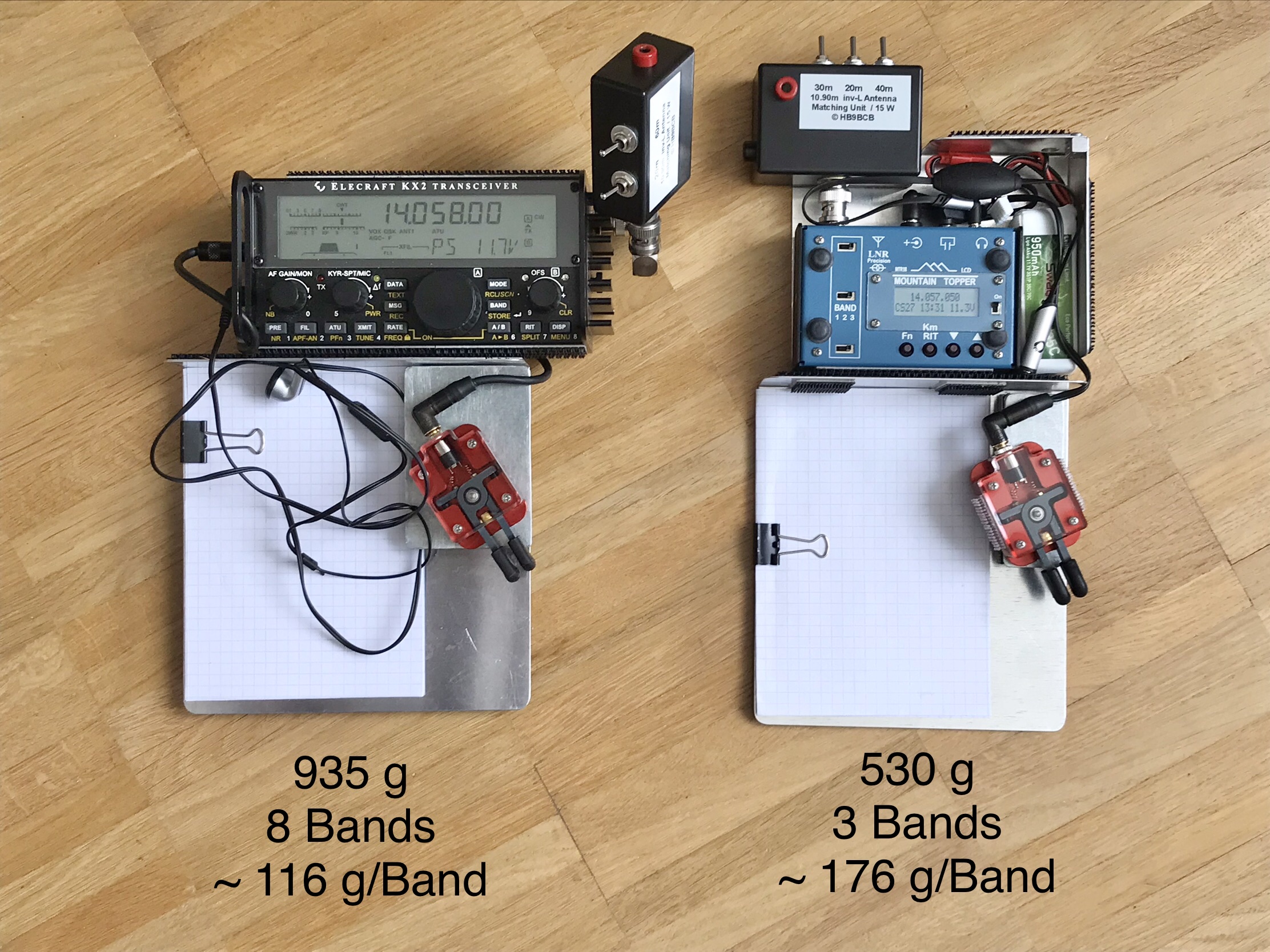
I planned the Z-match exclusively for the QMX and my 20m long EFHW with 1:49 transformer and 9m long coaxial. At 40, 20, 15m the swr is already less than 1.5 without a tuner.
But I also want to use 60, 30, 17m and the z-match should be used for that. Optimum efficiency on these bands is not possible due to the non-resonant antenna and the incorrect transmission ratio of the unun. And on 60m the operator is a essential part of the counterweight. (It’s tingling in my fingers, hI).
But with this unprofessional concept, I have always work the audible summits at 60, 30, 17m with my KX2 and internal tuner. My soft spot is “Make it as simple as possible while it still works”
73 Chris
With my QMX transceiver, I use an Emtech ZM-2 antenna tuner (Z-match) for bands where I don’t get a naturally low SWR with my EFHW antenna. What I do is get minimum SWR settings using an antenna analyzer on my ZM-2 with my EFHW set up at home and record the settings for all bands on the normal frequencies that I use. When I get out in the field all I have to do is set up the ZM-2 to the recorded settings for that band. Upon transmitting, I tweak one or both of the tuning capacitors to get the true minimum SWR. If you have trouble with the SWR threshold shutting you down initially, you might consider setting the threshold higher. Hans has indicated that the SWR measurement on the QMX may not be entirely accurate. This process helps get around the initial shut down from high SWR that you might experience with the QMX with random tuner settings
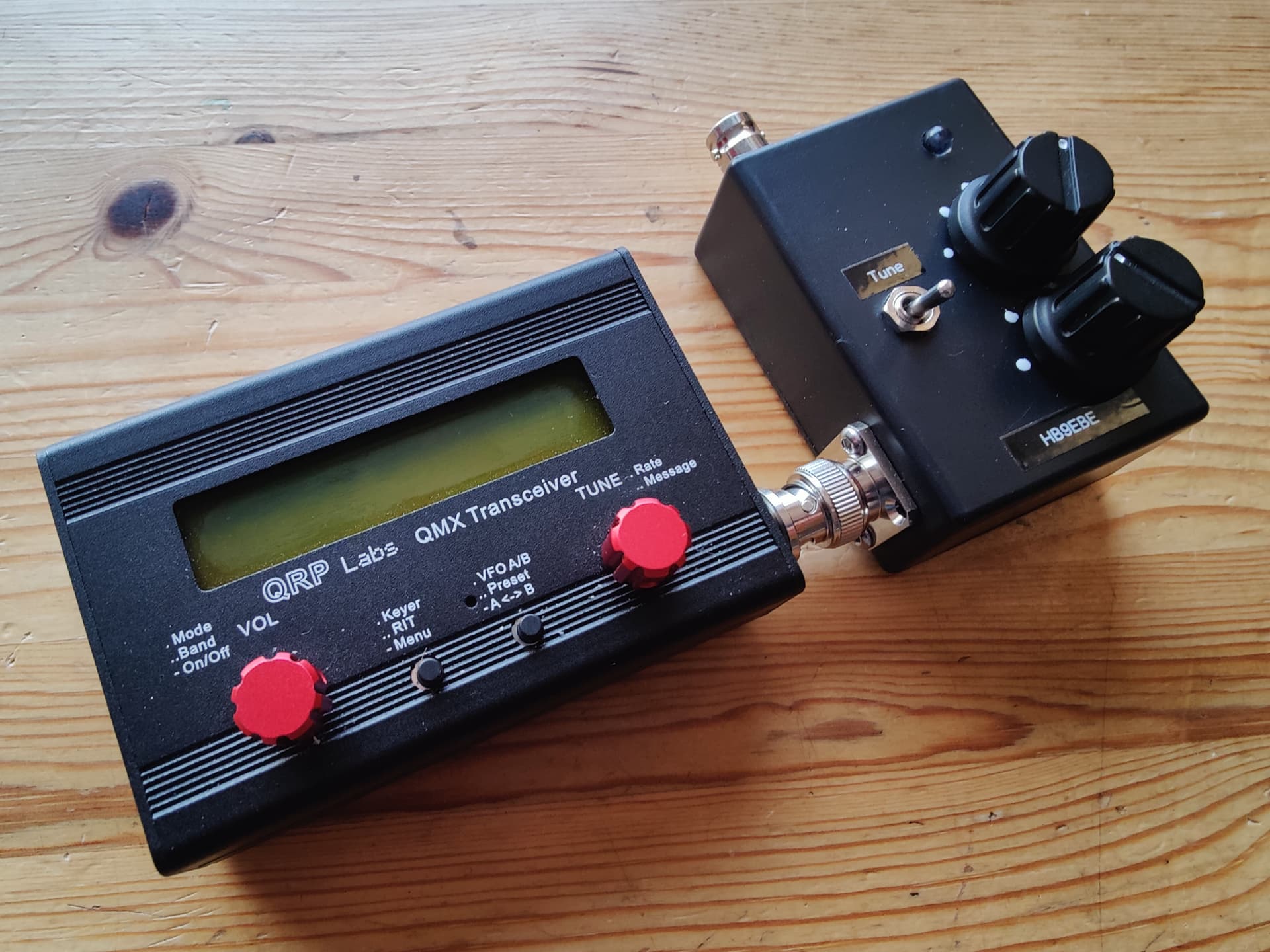
A very well done design, considering the arrangement of the BNC socket on the side of the QMX.
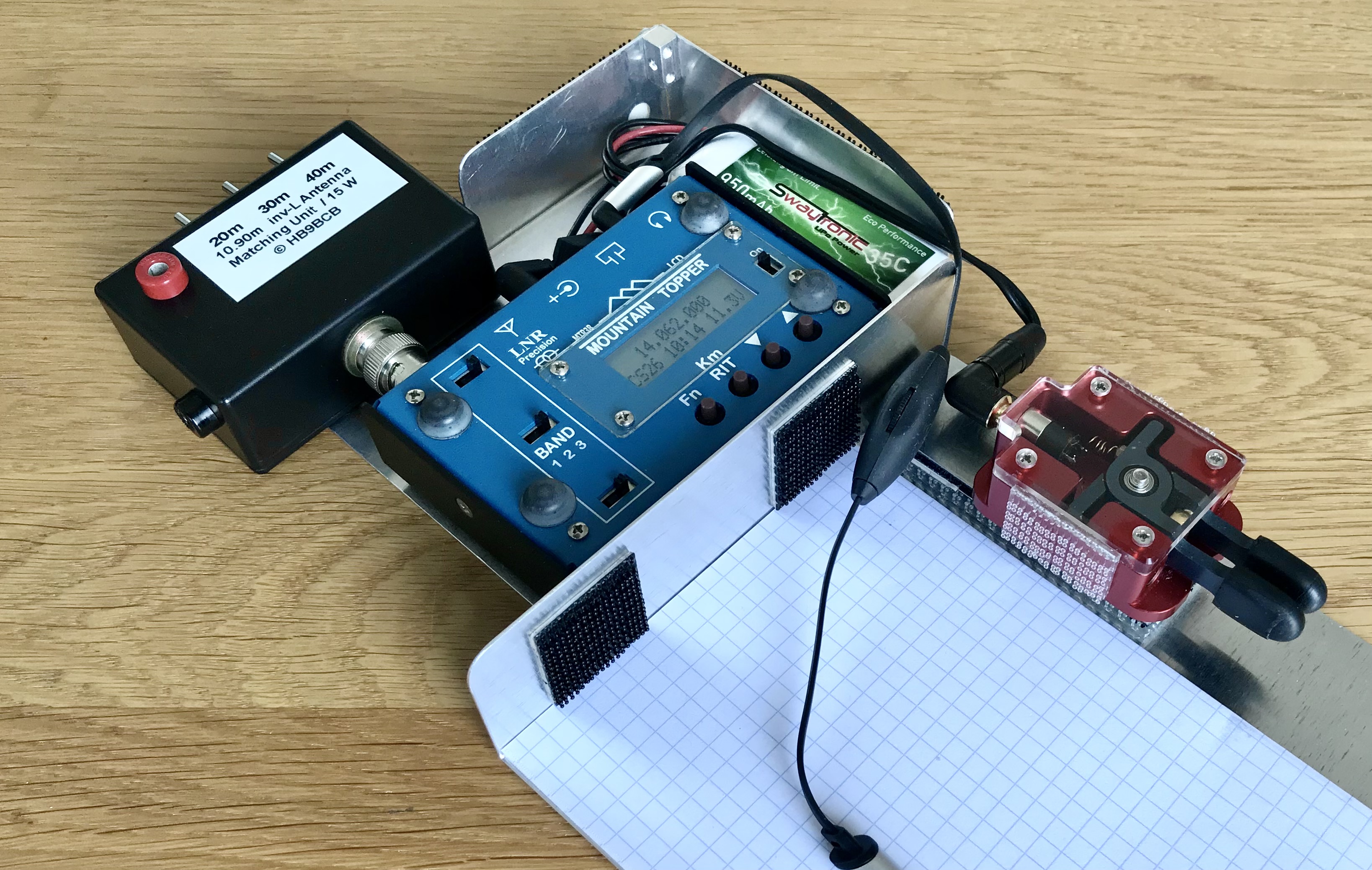
… and only 82 g light, exactly the same weight as my 40/30/20 m L-Match for the MTR3B, hi (which is also usable with the QMX …).
BTW, I did another weight analysis a while ago, just like that… of course there would also be the volume of the setups, which also have an influence on the size and weight of the backpack, hi.
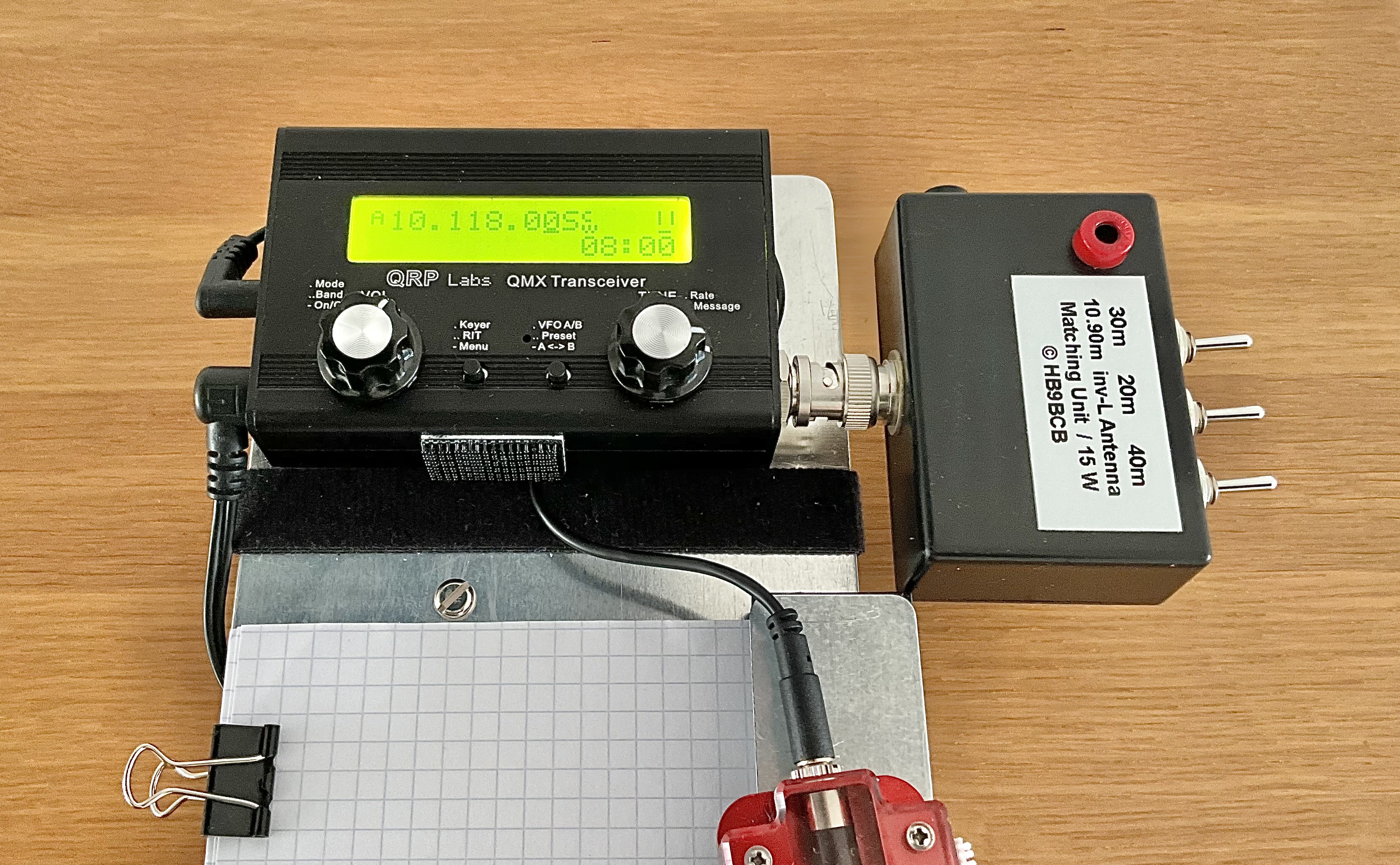
I really like your set-ups! The aluminium board will be my next copy … Would you have the plan/details of your matching unit for the 10.9m inv-L? Do you need to adjust depending on the soil or make the 4 CPs that unnecessary?
Thanks for the interesting links Heinz. Seems Lloyd popped his clogs this year, so a fitting memorial to him.
Why don’t you ditch the unun, and connect the EFHW to the top of the coil?
The unun is adding nothing but loss. (except for allowing the short bit of coax)
On the resonant bands this will be ~= to matching 113 ohms (N=28/8, Zequivalent = 50* (7/(28/6))^2
On the non resonant bands another tapping point might be better.
The nett result is probably a lower loss than the broadband unun alone.
Hmm - I just noticed you have 9m of coax!
That sort of turns your antenna+coax into an end connected OCFD at 60m,30m,15m
You would probably choke the coax at ~7.5m for 60m resonance.
You could put a relay* at the Unun to switch it out of circuit or to a different ratio for OFCD mode.
A quick play at portable-antennas - OCFD antenna designer suggests OK swr with a direct coax connection (no 4:1) at 60,30m.
Adding it to my NEC2 EFHW model shows the OCFD mode giving 60m and 30m with a 350ohm match (3:8 turns) with 17m possible if the choke point is closer (<7m)
Another way to use this basic setup, would be to use the coax+wire as an EFHW for 60,30,17m.
i.e. have ~7m of coax feeder (i.e. coax+antenna = 60m 1/2wave, and the 7:1 EFHW transformer as usual). When you want to use 60,30,17m, you feed both the coax inner and outer together as an EFHW. This has the beauty of having a band switch at the radio end of the coax.
Except how is it a feedpoint band switch if you then have to physically move the UNUN from the far end of the coax to the 7.5m point each time you switch bands? Or am I missing a trick?
That’s clever. I currently run an EF40mHW with a ‘counterpoise’ the other side of the feed point to turn it into a 60m OCFD. I have to walk to the feed point and switch the UNUN between EFHW and OCFD mode. But it’s nice & simple. But with your suggestion I don’t even need the counterpoise, just a choke in the coax.
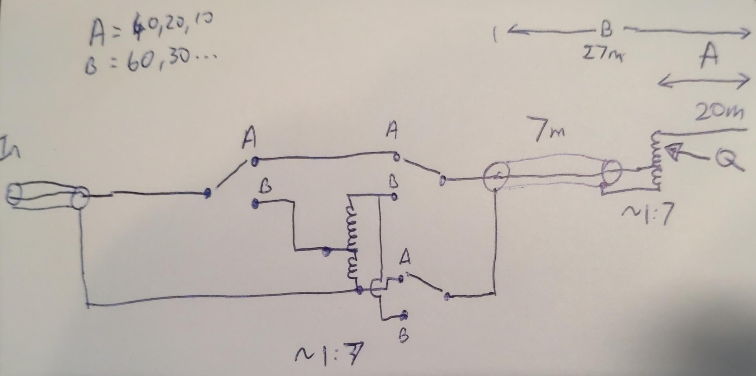
One in the antenna where the coax ends and the wire begins. This is used when the wire alone is the EFHW (40,20,10) (A in diagram)
The other is at the at the radio end of the coax. This is used when the coax+wire is the EFHW (B in diagram)
When the coax inner and outer are connected, the transformer primary is shorted via coax, but there is some leakage inductance labelled Q on the diagram. This is a complex situation. Perhaps this stops the idea in practice?
This arrangement is an EFHW for 60,30,17,12 . Perhaps. i.e. being an EFHW for the 60m++ band set, might give you more bands than being an OCFD. Or maybe not - I wouldn’t trust the modelling very much.
The other point about the OCFD arrangement, is that the ratio is set by the resonant length of the EFHW part, so you are going to get a feedpoint of ~26% , you don’t get to choose it for best multi banding as you can in a pure OCFD.
This where you could put a relay to make the tap change switch. If you put 2 relays there, you could have a choice of Z’s
One thing about EFHW’s is that the Z of the higher modes is different to the fundamental, so having a choice of two taps would likely improve the match, and make it less of a compromise.
I imagine you sitting under the feed point with a short 3m coax like I do, so you would only have to stand up. How are you using it that you are far from the feedpoint?
So playing in NEC a bit more, your arrangement has the advantage that it can be tuned multiple ways in the counterpoise when in OCFD mode. (c.f. EFHW which is tuned/loaded at the far end)
you could have ~7.5m counterpoise (60,30) with a link at ~5.5m (17m,12m).
you can put a loading L in the counterpoise and have the counterpoise shorter than 7.5m for 60m, trim 30m, or tune it down to 80m
series C can make the 7.5m counterpoise work for 17m
an LC trap can make it OK on 60,30,17 at the same time.
I don’t even bother with a link. The counterpoise is tied to the guy cord at the 17m resonance point. I fold & wrap the remaining wire back up the counterpoise to run 17m. I extend the remaining wire and hook through a loop tied in guy to run 60m. Low tech but fewer things to get tangled when I need to pull it through scrub winding it all back onto the winder.
For the same reason I don’t use the bits of plastic at the apex of the wire that people seem to like to attach to the mast - just a small loop in the antenna wire to hook onto the top mast section.
Never thought to try 12m and not CW competent so don’t yet use 30m portable. One day!
Yeah I prefer to have just plain wire in the antenna - no plugs, no soldering. I use a crocodile clip attached to the unun, which has been good. And a clove hitch onto the pole.
What size coax do you use?
Do you use any of the DOC channels i.e. out of band frequencies?
The loss of RG316 is not that much better in HF (the advantage of RG316 becomes greater in VHF).
However, teflon-jacketed coax are considerably more durable and requires much less repair/replacement than PVC-jacketed variety. I use teflon jacketed antenna radiator wires and coax and don’t want to go back (easy to pull through tree branches, too, due to non-stick).