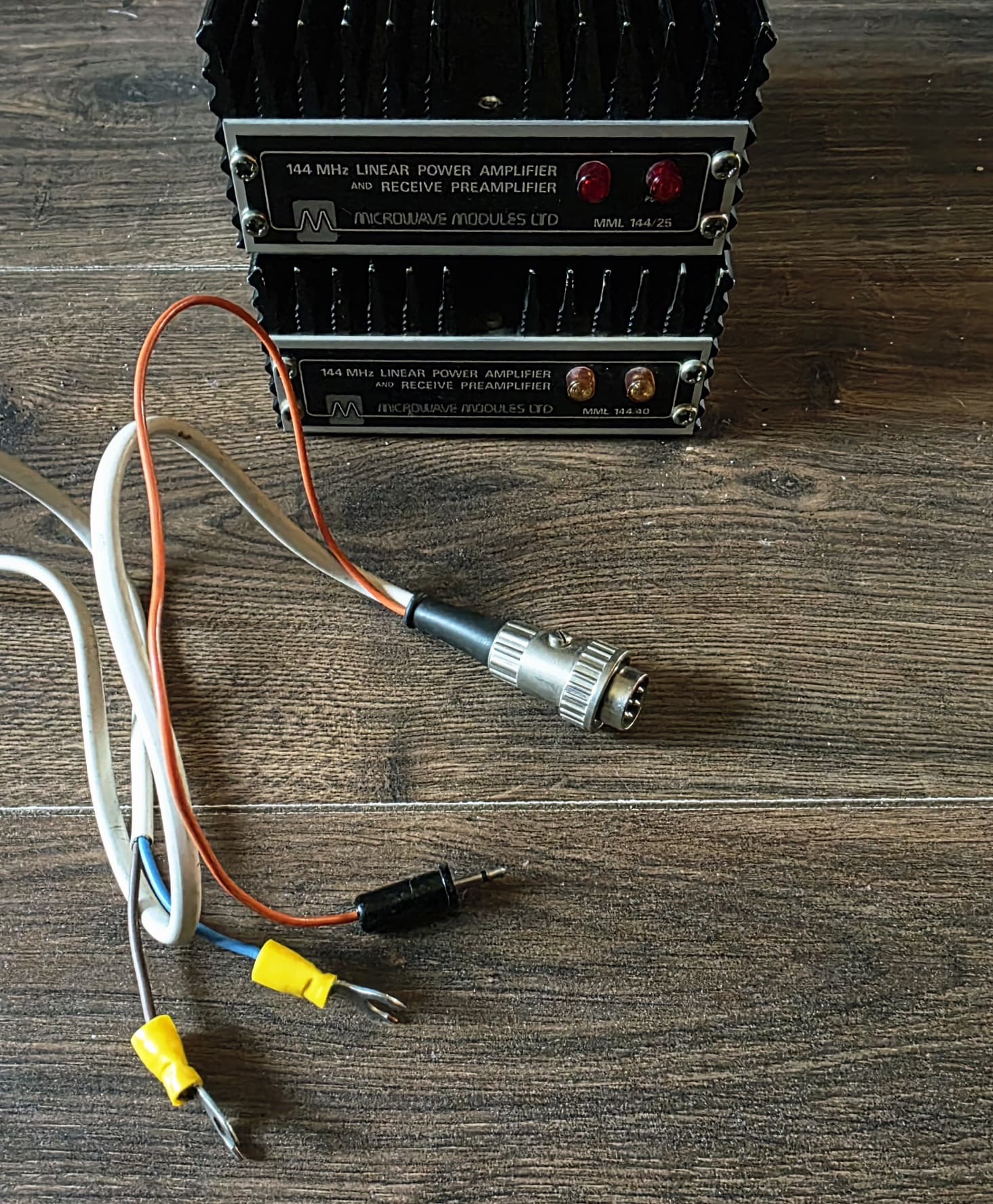
I’ve developed an unhealthy interest in acquiring VHF linear amplifiers, and today received my third VHF linear amplifier, and the second made by Microwave Modules.
Joining the party of the Yaesu FL-2010 and MML 144/25, is this handsome MML 144/40.
Thing is, what in the absolute boggling trousers is this cable the seller lobbed in the box? The connector is the same as my MML 144/25 one, but the wiring looks like it was pilfered from an extension lead! And what in the name of exploding omelettes is that orange cable dangling precariously out of the connector!?
Needless to say, I am not going to be putting that thing anywhere near my precious MML amp! Does anyone know though what the heck this cable is supposed to be?
I just hooked up my existing (now powerpoled) MML 144/25 cable and the new amp powers on just fine.
Just need an MML 144/30 and an MML 144/100 to complete the set now. Then I’ll accidentally on purpose have to get the UHF range of MML amps next…
PTT? Nope. I’m lost there. Is it to help trigger PTT in some way? Genuinely keen to know as I’ve not come across a cable configuration like this before.
The 2.5mm (mono?) orange cable dangling out from the bottom of the 5 pin connector. My mind is thinking about the FT-290 stand by jack now!
PTT stands for “press to talk”, which doesn’t help understand this useage! It generally refers to the mechanism of changing from rx to tx.
The linear has to pass signals from the antenna to the radio on receive, but on transmit, it has a relay or two which change the rf flow to run from radio through the amplifying device and out to the aerial.
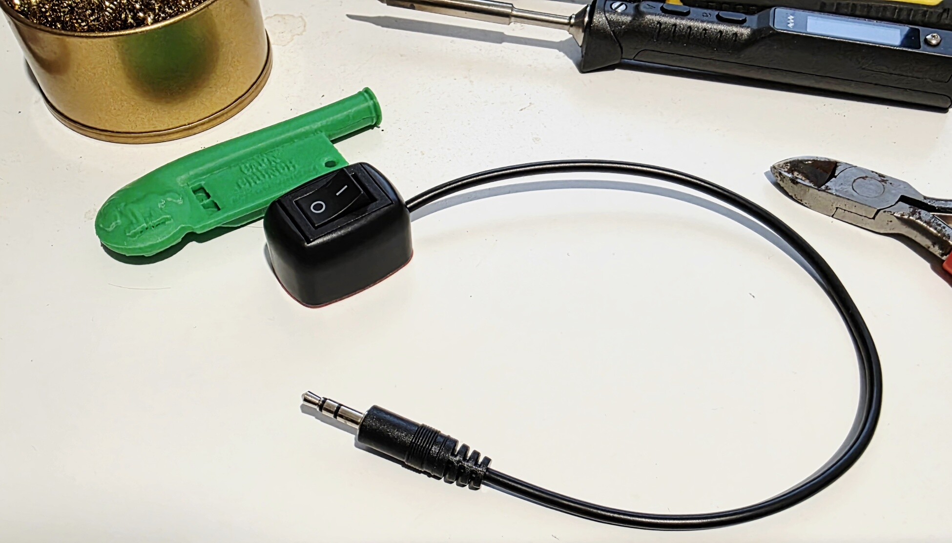
Operating this relay is accomplished typically by connecting the amplifier’s PTT line to “earth” eg the metal chassis etc. That’s what the orange lead and jack are for.
(It won’t work with the ft290 standby connection, because that is also a PTT “input” to switch the 290 into tx mode, not an “output” to control a linear)
Some linear amps like these also have “rf sensing” , which means that the amp relay(s) switch over when it senses a whiff of RF coming from the radio. This can be quite usefull for FM (where there is a constant RF carrier) but might be annoying with CW or SSB unless you can set the delay time eg how long it takes to revert to RX once the RF has stopped arriving.
No omelettes have been sacrificed in the typing of this reply.
Thank God for that I was beginning to get worried!
Ah so it’s just an Earth connection, gotcha. Thanks for this, I saw the mono audio plug and it threw me! I’ll just chuck it in a spares bin so, and use my powerpoled MML cable instead.
Fair play to the seller as they put a note in the box and said the MML 144/40 will only take a max 10w input (the 144/25 takes up to 5w in case anyone was wondering).
This means the 144/40 could handle a Tidradio H8, I might test that out soon with the H8 I have already.
Probably a daft question, but could you stack/chain linear amps? I’d assume not but just wondered as you could then theoretically have a chain of FT-290 (2w) > FL-2010 (10w) > MML 144/40 (40w)!
You could do that, but it wouldn’t be the best way to arrive at 40W output - it introduces several unnecessary points of failure.
Also, some of these may have receive preamps, and you wouldn’t want to stack those - the gain would be excessive and spoil you radio’s ability to handle big signals.
I’m picturing a huge pile of increasingly large amplifiers being photographed for the Guinness book of records as a pan of omlettes sizzles gently on the aerial array….
I had an issue driving my MM144/25 with the FT-817 on 5w. It didn’t like it at all, but was quite happy with 2.5w.
I also bought a 144/100 cheap, but it doesn’t work. I did look inside and there was a resistor just only connected at one end. Its now in the “one of those things I’ll get to at some point" drawer. At least I;ve got a metal box with a heatsink built in, and who knows, the power transistor might be good.
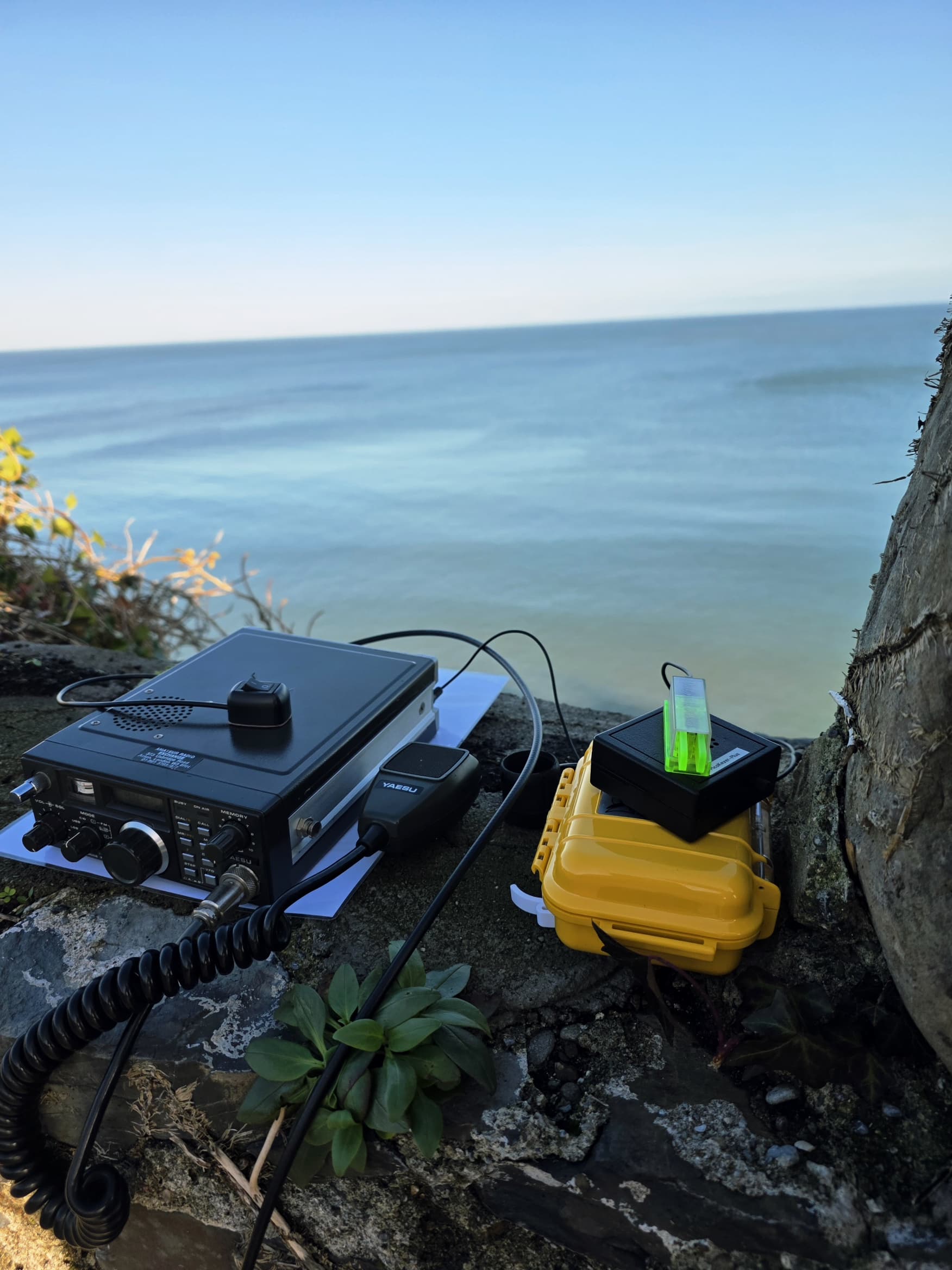
Calling CQ on 2m CW this weekend with the 144/40 in tow. Expect brownouts!
Bad news. I just discovered there is an MML 144/200 in the range as well. Looks like another one to add to the list!
I just tested the 144/40 with my FT-65 and FT-60 and both seem content enough with it.
I think that might have been what Andy was on about in a different thread that I’d get a tonking for using the amp and generating an SSB signal that spans about 6 different time zones with each over!
No, I don’t think so. Although I need to find a better solution, up until now, I have my key connected to the Key socket on the back. Separately, I have a cable going from the Standby connector to the transverter and I key the PTT using the microphone.
I’m not sure everything is quick enough to key the PTT line and the CW to give break-in keying. Unfortunately.
You could put a switch across the cable between Standby and transverter though.
I drive my MML144/25 with the FT-817 on half power, roughly equating to 2.5W. Setting the drive power a little more accurately with the KX3 shows it needs 2.4W for full output.
What’s this?… are you starting a museum? I was heading that way at one time with BNOS amps, the collection now sadly being reduced to just one 180W 2m amp (which I usually drive to no more than 100W) and a 50W 70cm one. They’ve both been up summits, but are a tad heavy.
Speaking of SOTA Amplifiers, I have had this for a number of years. I used to use it for the RSGB UKAC contests from home when I had a VHF/UHF setup using my Kenwood TS-790. Rated output is 100 watts.
It was built by:
SOTA Communication Systems Ltd. 24-26 Childwall Lane, Bowring Park. Liverpool, L14 6TX
I think they must have been out of business for many years now.
Unfortunately it’s mains powered so I can’t easily use it for SOTA.
Is normally done with PIN diode switching and there’s at least one relay in the 290, not for RF switching but the RX/TX power rails. In the abomination being suggested there will be relays in the 290, relays in the 2010 and relays in MM amp. The 2010 uses the 290 DC switching voltage, so let’s hope the pre-butchered 290 still has the DC voltage present. Something is needed to key the final amp as nobody outside an asylum will be RF switching on a CW signal, even with a small hang time.
An amp which is specified as 10W in MAXIMUM for 40W out is a real gain monster. Put it back into the museum in the section marked “technical oddities”.
I’ve said before most of the 1980s black faced MM amps achieved nothing like the claimed power at decent linearity, sure your MM 100 may give 100W but it was well into compression and non-linear by then. For good linearity you would de-rate to 85-90% claimed power. And they want 13.8V not 12V or they’re even worse. It would be interesting to see just how much power the 144/40 produces with 2.5W or 5W drive. There’s scant info online about this model so it’s not easy to see what the PA transistor is to figure out what the real drive requirements are.
The questions remain on how are all the amps being keyed so the relays aren’t chattering away and what they will be powered with to minimise non-linearity.
They were just round the corner from Microwave Modules. I’m sure it was set up by former MM staff. You see them crop up for sale quite often so they must have sold a fair few.
The instruction sheet is typewritten and the circuit diagram is hand drawn and dated “May 1980”.
The power supply is the usual bridge rectifier and big cap but is then followed by a 7812 with a 1N4007 in the ground lead driving the gates of 3 parallel PNP transistors, so maybe 13 volt nominal power rail?
The single main PA transistor is a SD1416, but there is a later note pointing to it saying MRF245. Nearly all the caps in the PA tuned input and output circuits are shown as “Select on Test”.
Thanks for the info, but I don’t have an MM amplifier (but I do use a Howes HC220 & HC280 transverter with the 290R).
I wasn’t suggesting break-in keying, just that I didn’t think it would work by keying the PTT line. In my setup, I have to manually switch the PTT line (which also switches the transverter), then key the CW.
That’s right David, the mic PTT and the standby line are in parallel. Taking either to 0V keys the radio. Or key the radio with the mic switch and use the standby line to key the transverter. Then send away using the key.