Owen Duffy has once again commented on the EFHW Transformer Design due to a newly offered product. Nothing surprising and, as always, tough in the assessment, but still worth reading.
What a difference: Just using the widgets (select, slider) and tapping on a legend key and/or a data point (curve) compared to the capabilities of the HP-35 calculator, which became available towards the end of my studies in 1972, hi.
Hello Heinz,
thanks for sharing, I’m glad to add this info to some previous references for a better understanding of the EFHW feeders.
I am afraid that we will still see this bad toroid winding technique replicated for a long time, thus loosing efficiency and reducing the radiated power in the antenna…
There are tons of pictures leading to this bad design; it’s a pity!
I keep in mind some good advices for an improved design that has been shown for broadband transformers here in the reflector some weeks/ months ago.
I understand that some people live in a bubble, without realizing it.
But why do companies selling commercial products without researching the topic first? Do they do that on purpose, to fit into the bubble? A thousand flies can’t be wrong…
This is probably the least “problematic” issue I have seen, but simply unnecessary.
The worst errors I have seen that I remember:
using the wrong ferrite material for the intended frequency range
loose windings and crossovers
using insulated wire instead of magnet wire
adding a layer of tape on the toroid
not choosing a good core geometry, but using single “standard” FT240-43 toroids
choosing bad capacitors (usually specified for very high voltage)
not adding enough primary turns (too low primary inductance for the lower bands)
Many of the above issues will generally lead to a better SWR, but lower efficiency. If you want to use the coupler to warm your hands, then that’s fine
The transformation of the rf in the toroidal core is based on the magnetic field that arises around the conductor. This magnetic field strength decreases rapidly when the distance increases. Anyone who plays with a magnet for the first time has this experience.
The magnetic field generated in the primary winding is therefore greater, the smaller the distance between the wire and the toroidal core. The same applies, of course, to the conversion of magnetic energy into electrical energy in the secondary winding.
Therefore, the wire should be as close and immovable to the core as possible. This applies in particular to the inside of the toroidal core, because there the magnetic field strength is at its maximum.
73 Chris
With transformers in general, to have a low flux leakage and therefore good coupling, the turns should be tightly wound.
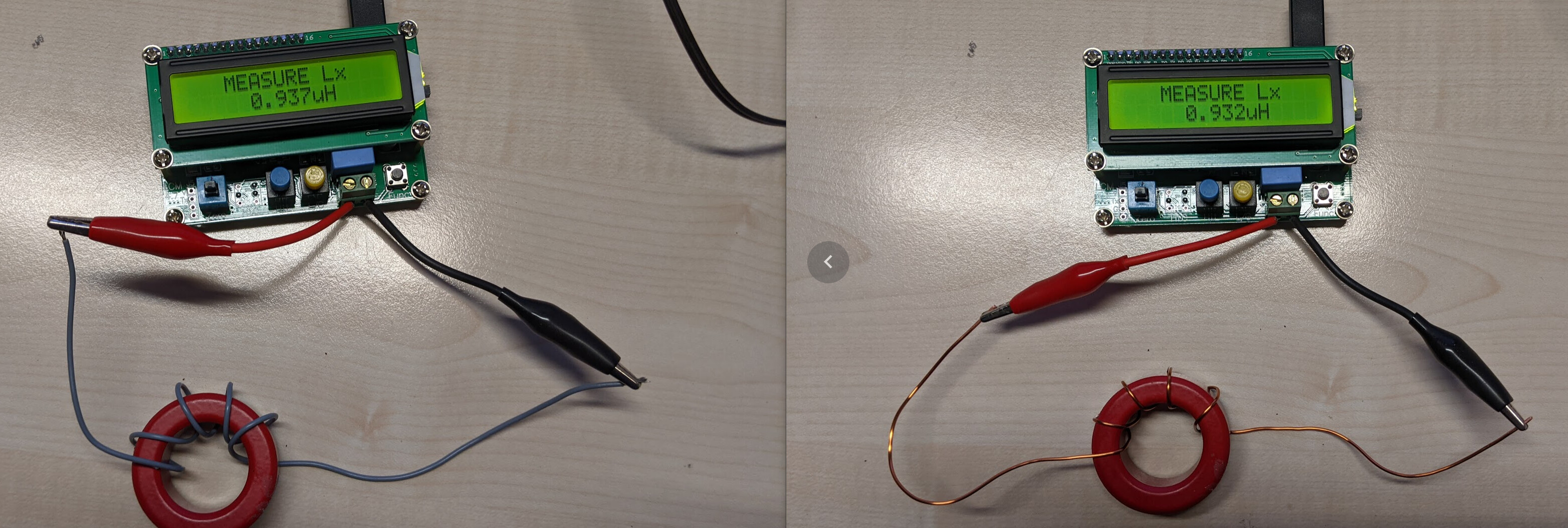
A video that compares and measures the two different winding styles:
Using insulated wires or adding a layer of tape increases the gap between the core and the wire (apart of adding another dielectric material).
The ferrite cores I measured are not conductive. By adding tape to the core, moreover you reduce its cooling ability.
There are also other winding techniques, that are already referenced in this thread and my document, but I didn’t experiment with them.
Many thanks Stephan for the link. The demonstration results are impressive.
Normally, you make a gap between the windings so that the capacitive coupling is smaller. Insulation tape is used at high voltages when the core is somewhat electrically conductive.
Agreed Peter,
The edge of the cores can be sharp enough to breach enamel wire. Teflon tape is recommended to reduce this problem. Unfortunately any old tape, some good, some bad, gets used. Teflon has low RF losses. The Teflon tape is very thin and makes no measurable effect on the flux enclosed. Available from plumbing stores.
Flattening the windings against the four sides of the core would have more effect than the thickness of the tape, although I’ve not seen this mentioned.
Insulated wires from CAT5 or CAT6 cable have low losses to 100 MHz. I use these for the primary winding and enamelled wire for the secondary. The extra intrawinding capacitance is less significant on the primary.
I think a compromise between spacing of turns to reduce shunt capacitance and keeping the winding short to minimise flux leakage may be necessary. I generally don’t have much spare winding space.
Damaging the wire can be done with any method if you are not paying attention to what you are doing. I think adding something that will decrease the performance for simply correcting builder error is a big tradeoff.
Hi all,
Many references are made to “enameled wire” Indeed, that’s what many builders use, because the enamel “dissolves” under the heat of soldering. There is a price for this, in reduced abrasion resistance against sharp ridges in uncoated ferrite or powdered iron cores. A far better magnet wire coating is Polyvinyl Acetal, e.g. “Formvar” or the like. It’s more expensive, and needs to be mechanically stripped. i.e. with sandpaper, etc. That said, it is really tough, and will withstand rough surfaces, the rigors of motor winding, and so on. I use it exclusively, and have one less thing to worry about in the field. It is available from Newark, Allied, etc,
From what I’ve read in other threads, the shape of the toroid is a big factor. You may be better off stacking smaller toroids so that you have a tube shape rather than using just one.
73 Matt
There are different ways to wind toroids. My statements were for small QRP toroid cores with the priority to get an efficiency of >90% across most bands.
I agree, that a thin layer of teflon tape doesn’t increase the flux leakage much, but is it necessary? I always try to strive for the simpler solution, if possible.
Where you definitely need some insulation, is when you make windings on top of each other and using higher power levels. This is what Gary Rondeau did with his specific winding technique:
Since the ferrite I used until now was not conductive, I don’t further insulate the enameled wire against it. I also never heard that somebody had a problem with blank wire touching the ferrite and using QRP, but I’m happy to hear the opposite. This is just my personal experience that I try to share.
I also agree with @VK3AFW that one should try to flatten the windings against the four sides of the core, which is what I did (as much as possible), by using a bit of force (and probably scratched a bit the enamel on the edges, which again, was not a problem). To me, this process is part of tight winding.
And yes there is definitely a compromise between spacing the turns for lower winding capacitance and winding very tight to keeping the flux leakage low. But with such small toroid cores that I use for QRP, there is not much place for spacing. Anyway, the spacing that is most critical is the high-Z antenna port against the ground port.
Hi Peter,
do you have a link for your L Meter? I bought a cheap component checker from Ali Express, not realising that they are useless for low inductances.
73 Matt