Back in the tail end of last year the MT announced that there’s be a Challenge in 2026, and that it would involve SSB and CW on 2 metres and 70 cms. I had, at home, an FM rig and a white stick. Clearly that wasn’t going to cut it. I got my hands on a small 2 metres transverter which works very nicely with my KX3. I tried it with the white stick with no success at all. I swapped the white stick for a 5-element 2 metres Yagi I had in storage. That worked a bit better, but it quickly became clear that antenna polarisation was an issue. Some activators were using portable Yagis which they usually deployed with horizontal polarisation, but others were using Slim-Jims or Flower-pots which generally work well only when close to vertical. I could, of course, change the polarisation of my Yagi, but the process involved ladders, spanners, and a certain amount of brute force. It was not something that could be done between QSOs.
I investigated commercially-available ways of changing polarisation at the flick of a switch. One solution involved X-beam antennas and multiple co-ax relays. Another just one relay and two separate antennas. The least complex option seemed to be simply twisting the antenna from one polarisation to the other, but no obvious commercial kit to do this remotelywas available. When I mentioned the problem during a Surrey Radio Contact Club (SRCC) Monday morning 80 metre Net, John G8MNY mentioned that Gareth @G4XAT had done something along those lines recently, so I dropped Gareth an e-mail. He’d recently won a prize in the RSGB Construction competition for his solution, which was aimed mainly at portable use, and its construction involved a fair bit of 3D printing. However, he also came back with photos of his solution and a whole slew of other ideas. I took some of them, most especially his suggestion that a good strong door hinge would be a good place to start, and put my lathe and mill to use.
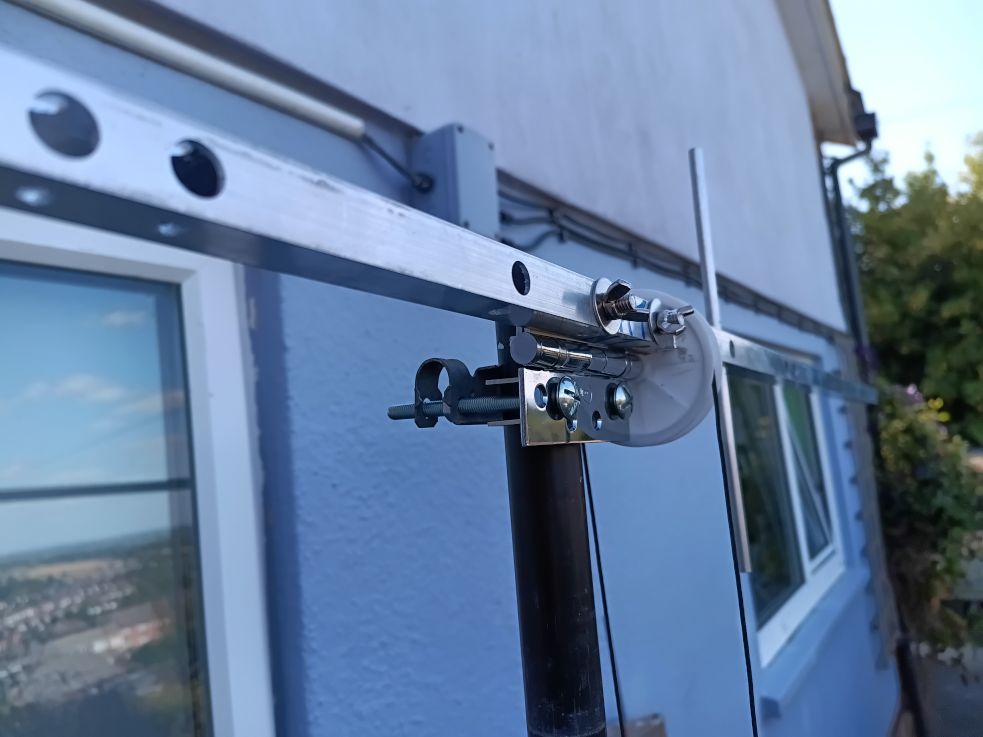
The primary pivot for my antenna is a heavy-duty door hinge attached so that the pivot line is as close to the boom as possible. I’ve used a plastic wheel with a hole cut in it to apply the turning force to the boom and hinge. The wheel’s axle is attached to the hinge appropriately. A long Dacron line wraps round the wheel and is anchored so that it won’t slip. Pulling one end turns the Yagi from vertical to horizontal. Pulling the other end does the reverse.
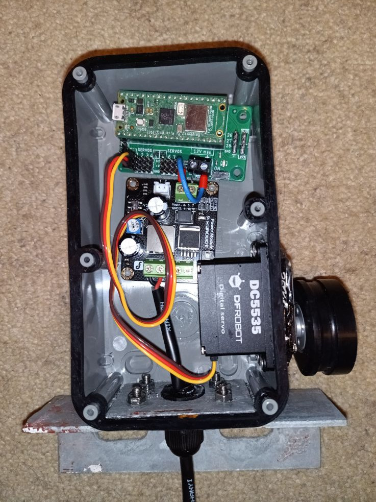
I’ve used a servo motor to provide the pulling force. The servo covers 180 degrees and the Yagi only needs to turn 90, so there’s a 2:1 relation between the wheel at the antenna and the pulley (which I turned on the lathe from a chunk of solid plastic) on the servo. The Dacron line goes round the pulley and is similarly anchored to avoid slippage. The servo is controlled by a Raspberry Pi Pico W.
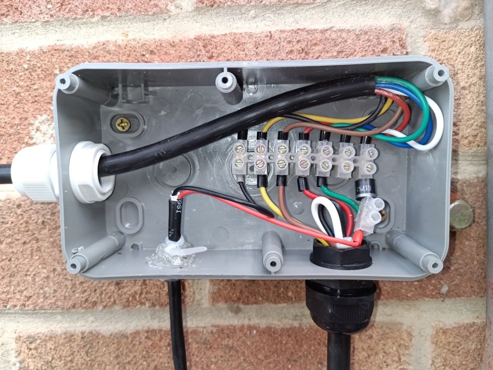
On the Pico W there’s a basic web server written in Micropython which serves a single page with options to set the antenna at a few selected angles. The only external wiring it needs is for power, which is comes from my auxilliary PSU back in the shack via a couple of spare wires in the rotator control cable. There’s a DC/DC converter to condition the incoming supply and feed the Pico and servo appropriately. The Pico W connects to my local network and is accessible only via a local IP address. It also only handles a single request at a time, but that’s enough for something controlling a single item.
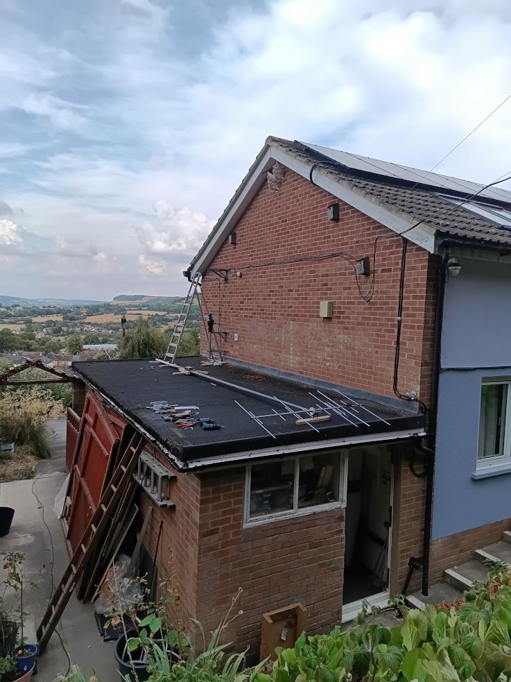
Parts of the project were delayed because a nesting box on the end of the house near the antennas was occupied for a while, but I finally have a Yagi that I can twist through ninety degrees from the comfort of my shack, and I’m looking forward to having the chance to do a little better in the last three months of the SOTA Challenge than I’ve managed so far.
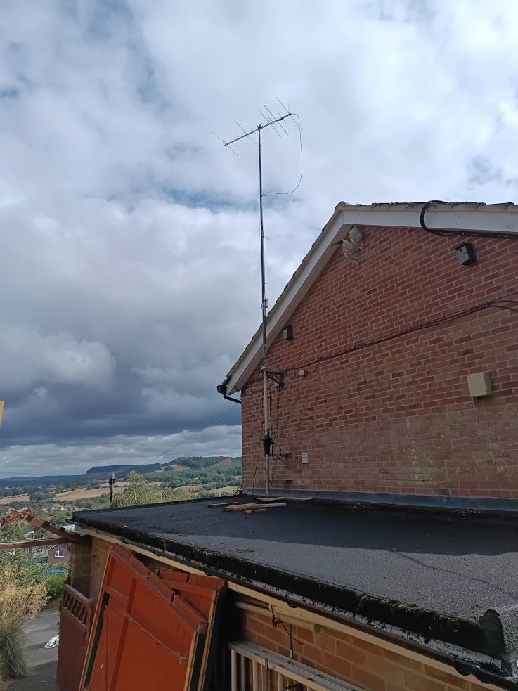
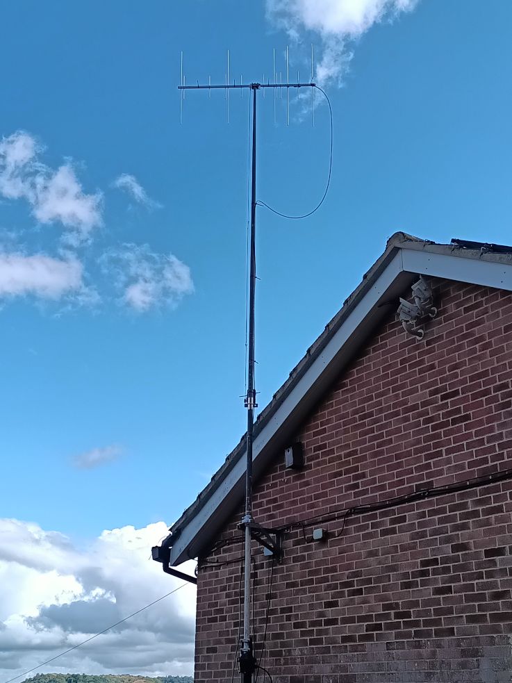
Inevitably there have been hiccups. One is that if the servo is not where the server expects it to be at the start of an operation then the servo tries to turn to that expected start position at maximum speed. Everything worked fine until the antenna got moved, possibly by an over-weight pigeon, magpie or crow. With the first set-up I had, when the servo needed to turn at maximum speed it tried to draw more current than the DC/DC converter that supplied both the servo and the Pico could provide. That in turn caused the 3.3V supply to the Pico to dip, and the Pico then ungracefully crashed. I had to get the whole lot down to find out what was wrong. The present version uses a different DC/DC converter which keeps servo and Pico supplies apart, and allows the servo to be supplied with slightly more volts. I’ve also modified the servo code to allow the “where is the antenna now” value to be re-written without turning the servo so that the system can be reset to match reality next time an over-weight pigeon uses the antenna as a perch.
P.S. Preparing the antenna’s EMF assessment was interesting…
 No rotators out in the field back in those daze…