I received my 4S battery with 10Ah just yesterday. I am currently resoldering the connectors and making a distribution box for my 50W amp and the 817ND.
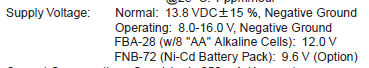
I measured voltage of 15V on the battery. I read that the Yaesu 817 will run on up to 16V. Since the voltage is 15V I personally see no problem here. I just want to check if anyone is running that “high” voltage on the 817ND for longer periods and if any issues appear doing so.
When a LIPO 4S battery is fully charged the voltage can go up to 16.8v. (LifePO is less). If yours is a LIPO, you can either regulate that down to the FT-817ND’s maximum voltage of 16v or simply, when charging the battery, watch the individual cell voltages and do not fully charge the cells so that the total voltage stays at under 16v. You will not see any degradation in performance of the FT-817ND running it even down at 11v !
Add 2 diodes inline to the 817nd supply and a switch to bypass when voltage dropped.
There is a thread here in the reflector that discussed it. Or there is also a suggestion using a switching converter that is not causing any HF interferrences.
I tried but can’t find it.
Hmm I have a Voltage down converter but it takes max 2Amps. Max voltage for 817 is 16V not 15V. I got that number from forums and the 14.8V from the website (see link above). I will hook up the battery to a charger and see whats the top Voltage after charging. I received the pack yesterday so I assume its not fully charged yet…
Battteries are normally shipped partly charged, so I expect the voltage when fully charged will be over 16v. I would recomend some method of dropping the voltage. I used to use 4 diodes in-line to get the 16.8v down to 14v from some 5Ah hardcase 4S LIPO batteries that I have. In my case, with the current being drawn, 2 was not enough - bear in mind the excess voltage is dissipated in heat, so you need diodes of the correct current rating. I have now changed from the diodes to an LM338T regulator circuit on a small heatsink.
My memory might be at fault here, so its worth checking the eye-watering circuit diagram, but the external power input to the 817 feeds a voltage regulator which drops the voltage to 9V. This generates heat. It is possibly a waste of effort having batteries that provide significantly higher voltages than the 9.6V from a set of Nicads since it will finish up at 9V anyway.
Unfortunately I am not really into reading such diagrams… I think that people would not mind adding diodes and regulators all over the world if this would really be the case.
I will charge the battery fully and see. I’ll get a diode or two to be on the safe side. Thanks for the help OMs!
To relate a problem I had 13 years ago when I was using an FT-857 with a 4S1P cell LiPo battery giving around 16.4 volts when full charged. I used this battery at that starting voltage on many activations without damaging the radio. However, due to doing this I had a failed Winter Bonus activation resulting in no damage to the radio. This was when using the 4S1P battery in a temperature that was around -4C. The radio would not turn on due to the high voltage source but only in sub-zero temperatures. The activation failed (G/NP-031) however on returning to my car I tested the radio on a standard 7 Amp SLAB battery and it turned on no problem. Then my friend Frank G3RMD sent me a zener diode to put in line with the power lead to the 4S1P battery. Voltage was now around 14 volts fully charged - there was no problem switching the FT-857on in sub zero temperatures after that.
I am charging my battery. I can switch through the status in the charger, it says end voltage 16.8V @F5JKK I am not sure how you could charge it to 15.52…
Anyhow, I stumbled across this article: Yaesu FT-817 | Yaesu FT-817ND: FT-817 Voltage Reducer for Portable Transceivers
And I ordered a batch of those diodes and will make a jumper cable with them when using the big battery.
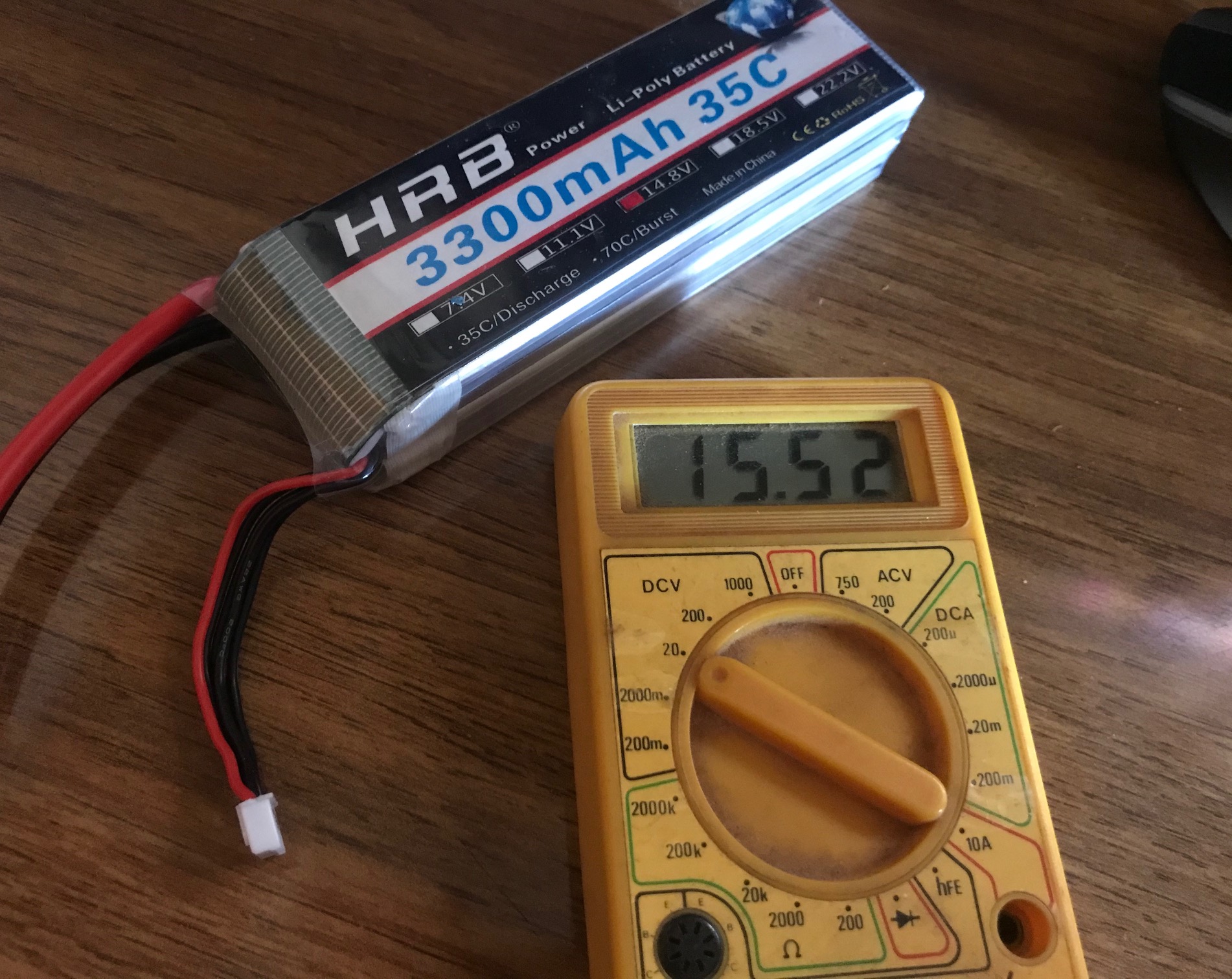
Hello - I have a similar arrangement as although the 817 is happy with 9V the linear isn’t, Started with a string of diodes to reduce the voltage, but really wanted something more foolproof as summit brain - or rather the pressuere to get back home before my pass expires tends to make me make mistakes. I now use a buck converter - mine is rated at 10A so it covers the amplifier too. It was a bit of trial end error on ebay to find one that didn’t produce stupid amounts of RFI but the current arrangement seems to work well. I am not sure of the efficiency but as it does not get anywhere near as hot as the diodes did . I also have a cheap battery alarm to stop accidentally killing the battery as the buck converter will always give the same voltage until the cells fail. I also found some batteries with a lower C value but the same capaity and less weight. As I’m not operating a drone I don’t need 50A so this seems to work well - so far.
I have regularly used my FT-817 with a LiPo 4S battery. I have a single 6A diode in series to drop the volts a little. The rig has never presented a problem with this arrangement, the only concern I have is if the rig is in the hot sun can it dissipate the extra heat from the regulator chips.
I also operate a Wouxun 950 on the summits, this needs the series diode to get the voltage below 16v because the internal protection circuit inhibits Tx if the voltage is >16v, however the Rx is fine even with a slight overvolts.
@G4VFL So how hot does the diode get? Is it a topic for concern?
@G4IPB that would be a box too much for me to carry. Why do you think diodes are not foolproof? Isnt it easier to use a couple of them in series in a heatshrink tube instead of hauling an extra box with you?
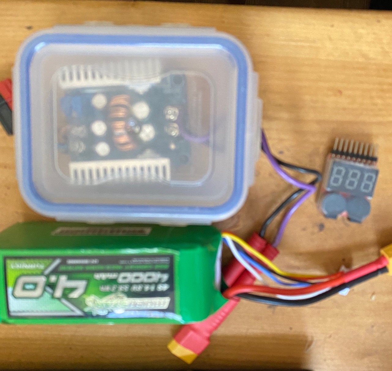
The FT-817 gets warm but not hot, however they are operated in the open on a summit so have plenty of cooling. The Wouxun does get hot on Tx (8A) but hasn’t failed yet.
They are soldered into reasonably thick copper leads to spread the heat into the copper lead.
I use the top one on the FT-817 and the lower one on the Wouxun.
When I was using 4 diodes to drop the 4S 16.8v voltage down to 14v for my Xiegu rig running 20 watts output (so 4 x the consumption of the 817), after about 30 minutes the diodes were too hot to touch and twice after about 45 minutes operation on a summit, the solder joints between them melted and the power stopped as one diode dropped into the bottom of the box. Even at these high temperatures the diodes were not damaged and the addition of some connector block instead of having soldered joints, solved that problem.
In contrast using the LM338 T regulator circuit on a small heatsink never gets even warm.
I had previously used a buck convertor - they are very efficient and don’t get warm but the models I tried, all created RFI which made radio operation difficult. One I had looked EXACTLY like the one G4IPB shows above - you can be lucky and you can be unlucky. My final solution was to go back to the old fashioned solution and use a component - a voltage regulator, which was designed to do the job.
Aleksander, a silicon power diode drops 0.9V typically. An 817 draws 2A peak typically. Worst case the power wasted in the diode will be 0.9*2 = 1.8W. me, I’d use 2 diodes in series to ensure I drop below 15V and remove them later when the battery voltage drops (use the 817 voltmeter to know when to switch them out).
Each diode dissipates 1.8W and a wire ended 3A diode (IN500x series) has a thermal resistance of 10 to 15 degC / W so expect a temp rise of 15*1.8 = 27deg C above ambient. Leave 2cms of lead and use a nice thickish cable and a lot of the heat will dissipate in the wire. But it will be noticeably hot to touch when you have been transmitting a lot, especially on FM.
Add some extra loss for rubbishy components and poor heat sinking and call it worst case 35degC above ambient.
Or buy a switching regulator from eBay but many of them produce a terrible amount of RF noise and it’s hard to know which to buy.