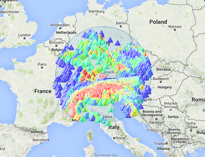
All being well, I hope to be able to get down to Ammerleite DL/AL-178 on Thursday afternoon to test out my shortened 80m dipole antenna.
Unfortuantely around 1300 UTC the band is short skip with a range of only up to 500 Km. If anyone hears me, I’ll be very glad of a report. Below is the expected range to be covered.
On 80M I heard you call at 53. Went back to you with one call, listened and then you were 31 at best and then I was defeated because of the noise level. Very strange indeed, I thought propagation but I saw your spot about kit problems so perhaps a combination of both maybe but thanks for trying 80M, it nearly worked for me
Thanks for going onto 40M - nice pile up!
Cheers
Mike
Hi Jan,
I suppose it does not really matter. Ed was testing some kit and I am interested in propagation especially modes/bands that are not very visited so…
I have lost track of what summits are valid or not - I just see if I can log them
Now off to walk Bertie the greyhound and then see if I can hear the SP/G team on the last summit today (valid!) which I think will be SP/BZ-082.
Cheers
Mike
Sorry Jan (and others), I was on DL/ AM -176 (NOT AL-176). The Summit code was correct in my Alert but I messed it up when I self spotted in the sunlight from the mobile phone!
I did announce the summit as Rentschen several times, strange no one picked up on it. I wonder if it is possible for SOTAWatch to not display invalid summit codes, then I would possibly have realised I did something wrong!
By propagation today, you should not have been able to hear me Mike - more than 500Ks at that time of day on 80m is unusual to say the least. Perhaps it was aircraft reflection, but I thought that could only occur on VHF?
My tests of the antenna were inconclusive. Mike G6TUH and Herbert OE9HRV heard me, but when I heard a faint reply, I took the Ramsey amplifier out of circuit and put the antenna cable directly into the FT-817, Herbert was there with a strong signal, but when I then went back to him with 5w rather than 30w, I didn’t hear any more. On receive, the amplifier should pass the signal straight through which it appears to do OK on 40 & 20m but not on 80m - this will need some investigation. Perhaps I should have tested JUST the new antenna and not the extended amplifier at the same time, but I knew it would be difficult to get contacts on 80m at that time of day, so I thought the extra few watts would help.
More work to be done, but if the antenna was getting a signl down to Bregenz and across to the UK, it can’t be doing too badly. It is a remarkably short dipole, so I am surprised it has worked as well as it apparently has today. Just need to fix the RX switching in the amp.
I’m following the tests and results with interest as I intend to try some 80m this Winter and a full size dipole is too much walking between the ends when setting up and taking down especially when I’ve already walked up a hill to start with!
Hello Ed,
I gave up a long time ago considering what I should or should not be able to hear and as a consequence my life is full of suprises When the K index hits the 5 or 6 I do think …hmm … though. Thanks for today.
Cheers
Mike
I am following this post with interest too.
Like you I have been experimenting with some coils for a loaded Inv-V doublet for 80m at home due to space restrictions.
My unloaded doublet is 8.3m per arm. Then I added the ~ 110uH coil and 2 additional meters of wire per arm.
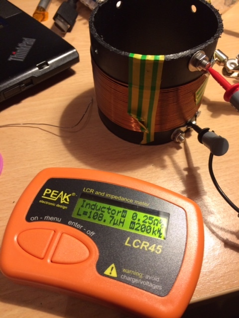
The coils were built using 35 turns of 0.9mm enameled wire using on a 80mm former
Calculated Q at 3.5 Mhz is around the 300 mark. Air Core Inductor Analysis/Synthesis
and some other quick calcs indicate that the overall setup resulting efficiency will be still low - .
I was playing with 4NEC2 to understand impedance @ feed point and other things of the overall setup but got stuck with other priorities.
The unloaded doublet design is described in my blog - 3r Apr 2016.
I know the feeling with the 80m dipole length, tried my 80m windom out on Sunday evening on Sharp Haw NP-29. I couldn’t get the long leg (87ft) of the ground high enough and had to keep walking back and forth to re-position it, only managed the one QSO on 80m and a few on 40m.
I may go back to my doublet antenna and add a link on each leg to extend to 44ft, carry the spare wire in the pack until needed. Think that is probably the simplest way to go for me.
Hi Angel,
It sounds like you are taking a far more organised and planned approach than I am! I am using coils with 100 turns on a 1" diameter plastic pipe in both legs of the dipole. The wire in the coils is garden wire, while on the portable version, the dipole itself is stranded connecting wire from the local elctronics hobby shop back in Australia (Jaycar). The home QTH version uses the same single strand (14AWG?) garden wire for the whole dipole including the coils, in fact there are just two pieces wire in the home QTH version, one on each side of the feed point - there are no cable joints.
On the portable version I tried moving the coil to different distances from the feed point to see if the distance affected the impedance. It didn’t. The impedance remained low at 32 Ohm and a 1.8:1 SWR. The home QTH version had an even lower impedance at 23 ohms and I have added a 2:1 Balun to that antenna.
What is rather strange is that the length of the portable version is quite a bit shorter at about 5m per side than the home QTH version at about 7m per side. Both use 100 turn coils on 1" plastic pipe close wound. Both are best resonant at 3.690 (the QRP frequency on 80m) but the home QTH version has a flatter SWR range and hence a wider bandwidth.
I’m sure someone can model these designs and explain why, what I am trying to do will never work well but for me the fun is in the trying and the fact that the portable shortened dipole antenna managed to put a 5-3 signal into the UK when propagation should have meant I wouldn’t even reach the French coast makes it really interesting.
The test was not conclusive due to some issue in the receive path through the small (30w) home built amplifier on the 80m position, which I have still to identify. The antenna appears to receive fine when the amplifier is not in circuit and on receive it “should” switch straight through (sounds like a broken wire or bad contact in the amplifier).
No doubt but never ever let any one tell you, you can’t do it till you try it for yourself and find out why but love that above picture of the gents 80m coil and the inductance meter would be an useful item in the antenna building of.
But not air me self till 20:00hrs utc and conditions were bit on the wow side on 40m working to Hungary and Ukraine and Italy and up and down the UK on inter G still at that time of day on a mere 10w and the home brew 40m f/w loop was a lovely experience, but the bigger buzz was hearing the Japanese stations with out a struggle man if i had reached one of those gents on 40m would have been a BIG first for me.
Damn that grey line was cranking out some stuff last night.
Thanks Richard,
That is exactly what I am doing. I have no doubt that I have probably gone past the limits of the recommended length, as in I have gone too small (and hence the impedance is low), but the resonant freuency is correct. I guess this means I need less wire on the loading coils (I currently have 100 turns close wound over 5 inces). The calculator is based on a horizontal dipole installation rather than an inverted-V but it should be pretty close, just requiring some final adjustments with the antenna anayser attached. As the article says the antenna is affected by the environment it is installed in and adjustment from the calculated lengths wil be required.
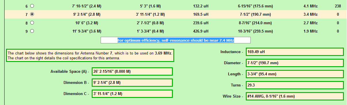
One question - what is meant by self-resonance? When I put in a set of values for an antenna to be resonant on 3.690, I get values given but then the text “For optimum efficiency, self-resonance should be near 7.4 MHz” - does that mean the antenna should appear to be resonant on 7.4MHz on the analyser??
I have inferred from the comments in the “possible configurations” section about self resonant frequency reducing with increasing coil size that this refers to the self resonant frequency of the loading coil(s) themselves. I’ve not been able to fathom the rationale for this figure or how it’s derived but there again I’ve not looked very closely…
I use the Peak LCR45 Inductance/capacitance/resistance meter and find it very useful for checking coils and toroids whose inductance can vary considerably even when constructed as per calculations :-s
Self-resonance will be the resonant frequency of the unloaded coil. You don’t want to operate anywhere near the self-resonant frequency. An electrically short antenna has capacitve reactance so you need to add inductance to make it electrically longer. Your coil’s inductance and self-capacitance will make it appear as a parallel tuned circuit at some frequency and its reactance will be inductive below resonance and capacitive above resonance.
I bow to your real and professional RF experience Richard. I did a little RF at university and have merely dabbled since apart from a period as the “EMC man” at work.
(You’d have to put them in the right place of course to give you quarter waves on 30m and I don’t know whether that would give practical values for the 80m antenna…)
thanks got it. If the coils have a self resonance near to the frequeny of the antenna, I guess they would act somewhat similar to traps and that is not the intention!