Can I have some advice on filters from people who are much smarter than me please!!!
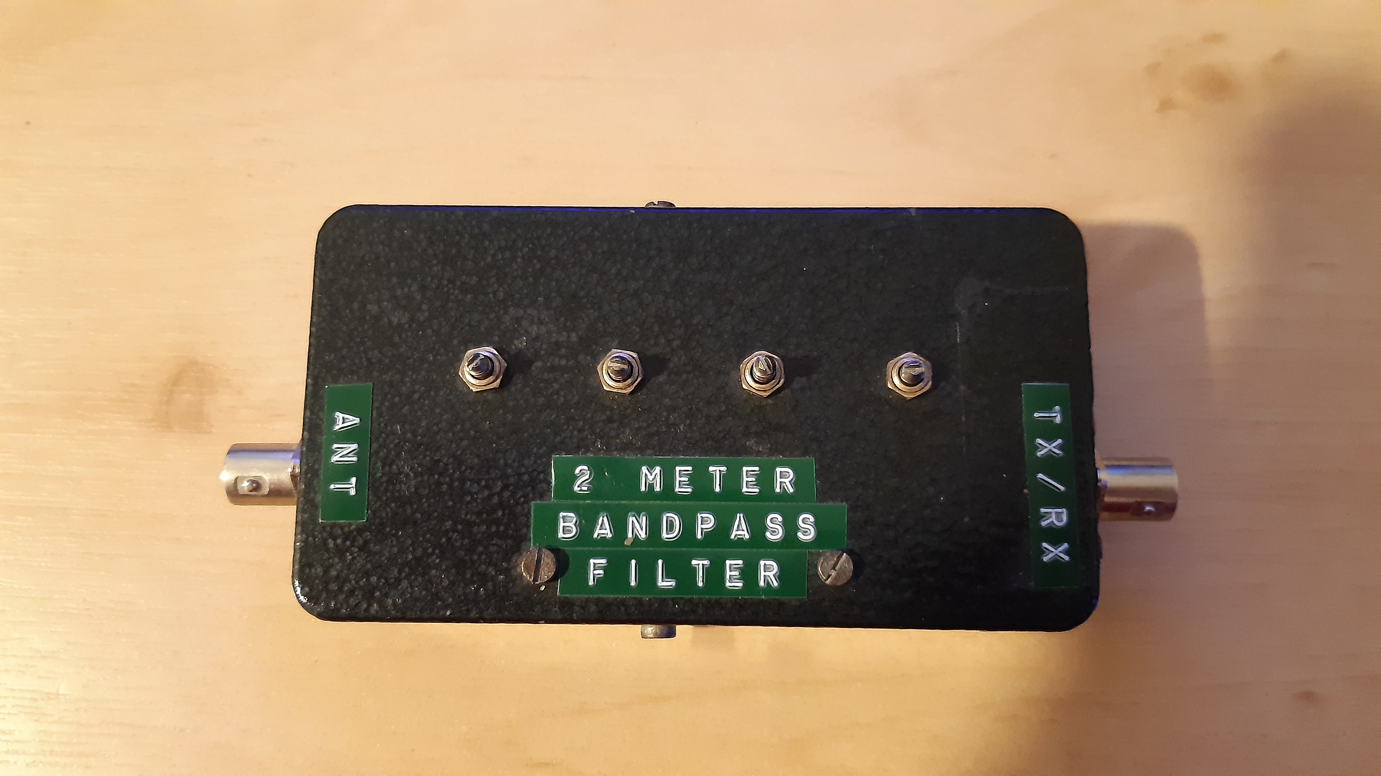
I picked up this 2m bandpass filter on Ebay several years ago for next to nothing (I think I paid 99p for the filter & around £1.50 shipping). I think it may be a homebrew that somebody has made at some point but I’m not sure.
I haven’t bothered to do anything with it until now but I’d quite like to get it working as it would be useful for 2m FM SOTA activations on summits where interference is a problem. I figured it would also be a good little educational project that I might learn a couple of things from.
It came with some weird antenna connectors, the likes of which I have never seen in my life. In my infinite wisdom I decided to replace them with BNC connectors. What I failed to consider is that snipping off the old connectors & re-soldering in the BNC connectors would mess up the tuning!
I believe most people use sweep signal generators & spectrum analysers costing thousands to tune these. I’m afraid that I don’t have such luxuries!!!
I’ve never tuned a filter before but undeterred I decided to have a go anyway. I set about attempting to tune it with my RSP1A SDR (using the SDR Uno Spectrum Analyser software which you can download from their website) & a cheap Chinese noise generator. I know it’s not the best equipment but it’s all I have available & figured that I should be able to get it close enough.
After a couple of hours tinkering, this is what I have ended up with on the spectrum analyser:-
As you can see, I got close (I aimed to centre it on 145MHz). No matter what I do I cannot get rid of that spike between 125MHz & 130MHz.
The tuning (piston type) capacitors felt extremely rough while trying to adjust them with a screw driver & the threads were slipping. I suspect that the tuning capacitors are probably knackered & need replacing.
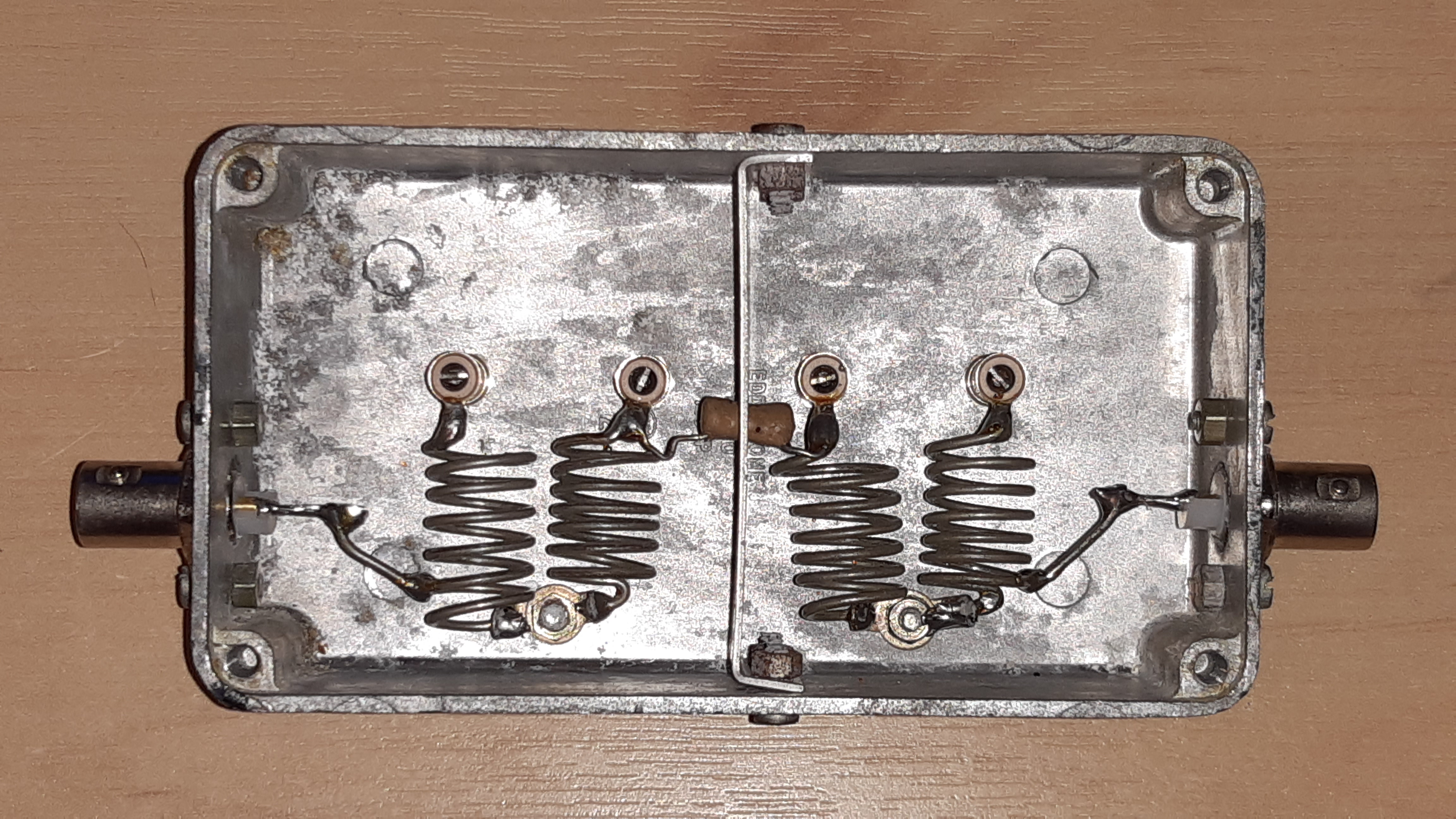
I’m also wondering whether it’s worth replacing the other component inside the box (looks like some kind of capacitor or maybe a resistor). The only markings on it are “1BA”. I’m struggling to find anything on Google which would give me any clues as to what that component is or it’s value.
Could I get some pointers on the following please:-
What type of filter circuit design is this? I know that there are a number of filter circuit types. If I can figure out what type of circuit it is I might be able to find some info online.
What value variable capacitors should I be fitting?
What is that mystery component in the middle & what value?
Does that spike that I can’t tune out suggest a problem with the filter, or is it a problem with the idiot trying to tune it?
Any tips for tuning this thing. Like I said, I have never tuned any filters before & I only have very basic equipment. That said, I would have thought that I should be able to get it close enough with what I have.
I would appreciate a couple of pointers to get me headed in the right direction.
Before using it as a filter for a transceiver, ie. for transmitting and receiving, I suggest checking the article to see whether it is rated for transmitting purposes. the small coupling capacitor between the two filter sections seems like it may be a low power component. ie, ok for receiving use but limited to quite low power. everything else will handle HT level powers. Good plan to change the connectors to BNC.
73 Andrew vk1da
●What type of filter circuit design is this? I know that there are a number of filter circuit types. If I can figure out what type of circuit it is I might be able to find some info onliine
There are 2 classic parallel resonant circuits with loose inductive coupling in each of the left and right chambers. They are coupled via a capacitor with a low capacity (mystical component). Input and output each by tapping at the cold end of the coil.
●What value of variable capacitors should I adjust?
Only a test can help here, as the geometric dimensions are difficult to estimate. I propose a variable capacitors with 20-30pF value. It could be hard to find some replacement. Try to turn it 10 times, so the dust and dirt goes away and the contact is ok.
●What is this mysterious component in the middle and what is its value?
Approx. 1pF to 5pF. Smaller values increase the filter sharpness but also the attenuation.
●Does that bit I can’t turn off suggest a problem with the filter, or is it a problem with the idiot trying to tune it?
Don’t worry about these artifacts. They are not generated by the filter. There will be secondary receiving stations (birdies) of the SDR.
●Any tips on setting this thing up. As I said, I’ve never set a filter and I only have very basic equipment. That said, I would have thought that I should …
Adjust the variable capacitors with a lot of patience and try to generate only one maximum at the desired frequency that is as narrow and pointed as possible.
But to do this, close the chambers with the lid.
The fixed capacitor between the chambers is 0.5pF and the trimmer capacitors are piston type 6pF maximum. It is designed for receive use or low power transmission.
It would be useful to remove the pistons from each capacitor and give them a good clean and use a (very small amount) lubricant when replacing them.
You could replace the trimmers with some small air spaced ones and it would then be usable for transmission
Thanks for all the pointers gents, that’s really helpful.
That’s what I thought but the extra peak confused me!!!
Awesome, that’s exactly what I needed to know. As this is for portable SOTA use, I will only be using very low power. I Typically use either a handheld with somewhere between 2.5 watts & 5 watts. When I can be bothered to lug it up the hill, I quite often I use my Yaesu FT-290 but it’s a bit big & heavy (compared to a handheld).
I think I’ll replace all of the capacitors just to be safe. What sort of voltage rating should I be looking for on the capacitors? Will 1000v capacitors be ok for up to 5 watts FM?
Hi James,
The trimmers should not need to be replaced, I think they are basically an air gap capacitor with ceramic insulation. The small coupling capacitor would also be a ceramic type, not subject to the type of degradation other types of capacitor suffer. I think it’s a good idea to refer to the article in the VHF/UHF manual - it may have been intended for receiver use between a preamp and a converter, which was a typical use of such filters. Someone you know will have a copy and could give you a copy of the project article.
For receiving applications especially following a preamp, a few db of loss in a filter like this is immaterial as the preamp probably has 20+ db of gain. But for transmitting purposes, you won’t welcome any loss more than say 3db, which would probably be regarded as a fairly low loss filter.
I’ll be interested to see how it works out.
73 Andrew VK1DA/VK2UH
If you need a copy of the schematic PM me and I will send you a scan.
1000v is definitely overkill - I would leave well alone (see VK1DA comments above)