Richard,
Please read EA2BV’S current thread on this Reflector. His tuner is similar to my more complex tuners, and he’s getting good results with his basic circuit with one tuning capacitor. If you get your wire to be resonant and use his circuit, you should be OK.
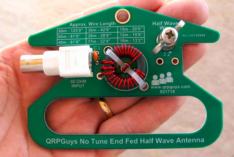
You may be able to get the QRP Guys tuner to work also, by trial and error. I agree with others that getting rid of the coax and maybe the counterpoise is worth trying.
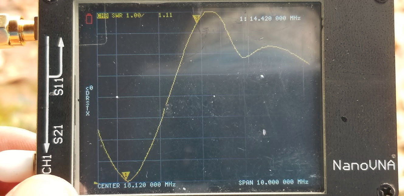
It is very tricky to use any kind of analyzer designed to work near 50 ohms to analyze a high-Z end-fed wire. The wire does need to be adjusted closely for good results with a no-tune matching circuit. However, with just one variable capacitor and a parallel-resonant circuit, as used in EA2BV’s tuner, you can compensate for small errors in cutting the wire, as well as variables on your site up on the mountain.
I mostly use a more complex tuner, with the same BASIC basic circuit as EA2BD, just many more variables, and I can tell you that there are CHANGES in the matches from one SOTA site to another that really do affect the matches I must use to get perfect SWR to me radio, almost always:
Ground effects
Capacitance at the feed end
Capacitance at the far end
Height of the wire
Running the wire close to rocks
Bends in the wire
Tree limbs
Carbon pole or not
A single variable capacitor gives you some control and ability to correct for many minor changes.
If you want to run a single wire on many bands, in many configurations, with no links and no counterpoise, you need a tuner with more variables. This is what I use, and I think it makes SOTA much easier. A auto-tuner in your radio can help, and it may provide all you need for some wires. An auto-tuner combined with a broadband step-up matching device to an end-fed wire is another effective way to deal with the realities of getting a signal into the air on various bands.
A quick word on counterpoises used with resonant, end-fed antennas:
If the antenna is really resonant and high-Z, fed at one end, near ground, a counterpoise usually has almost no effect on the match. I have done this experiment many times when using my own high-Z tuners. This means you don’t need a counterpoise in that situation, and it adds no value.
On the other hand, if your antenna is not actually high-Z resonant, a counterpoise may have some effect. In particular, if your end-fed antenna is low -Z resonant, such as a quarter-wave, or 3/4 wave, a counterpoise of about 1/4 wave will have a large effect, because it creates a low-impedance feed. The counterpoise is the second wire of your antenna system. However, for this special case, you MUST have a low-Z tuner designed to feed the new configuration. If you adjust the lengths of one or both wires, you should end up with a nice, low-reactance match for your low-Z tuner, and it will be very effective on the band(s) for which it is resonant.
In order to use more bands with a single wire, counterpoise or not, a more complex tuner should be used, and there are many designs that will work, depending on all the variables and details.
The really cool thing here is that a less simple tuner with several variables, like the tuners I use, will actually match the complex impedances presented by a single wire on many wavelengths, even without a counterpoise, and the radio sits there looking at 50 ohms, and the signals go out with surprising efficiency. For most SOTA activations, I feed a 65-foot wire on 7.030 and 14.060 MHz, where the antenna is approximately resonant and a half wave or full wave. Then I QSY to 10.110, change the settings only a tiny bit from the settings I use on 14.060, only a little less tuning capacitance in the resonant circuit, just change ONE VARIABLE, and I’m on 10.110 with a perfect SWR, even with no counterpoise. This is a happy good-luck thing. The 65-foot antenna is very reactive on 10.110 MHz, it is NOT RESONANT by itself, but with the tuner adjusted, the SYSTEM IS RESONANT, and there is enough capacitance to ground in my wiring and body for the reactive currents to complete the circuit with the tuner. It all works even sitting on top of 4 or 5 feet of snow.
F4WBN can contact me from EU when I am running this system in the middle of the day on 10.113 MHz. He has done it several times.
Resonant low-Z antennas may work without a tuner when center-fed.
Resonant high-Z antennas may work with only a simple tuner or matching transformer, when end-fed.
Non-resonant antennas may work with only a simple tuner when used with a matching resonant counterpoise, or even without a tuner, in special cases.
Non-resonant antennas can work well with more complex tuners, with or without a counterpoise, over a broad range of frequencies. This includes both balanced and end-fed designs.
End-fed designs that use more than a few feet of coax are special cases, and the entire system must be included in the analysis, including RF currents on the outside of the coax, as well as inside the line.
Any design that includes a conventional transformer made of type 43 ferrite may have significant loss on some bands. When people mention that the core may become warm or hot, we are talking about significant loss.
Resonant tuned circuits help avoid RF loss in the toroid core, IF they use type 2 or type 6 powdered iron cores. Circuit loss can be reduced by not using too much capacitance, using the correct amount of coupling (another variable), and by using slightly larger cores than what is needed for the power level.
That’s enough to get started. Beware of simple answers for a complex system.
Complex numbers describe the reactive currents we deal with in our portable antennas for SOTA. The voltage and the current are seldom in phase! To change the resistive in-phase 50-ohm output of a radio to force a non-resonant wire to radiate efficiently, we need several components adjusted to produce the correct voltage, current, and phase to drive the wire with a complex signal - voltage and current are NOT in phase - and we want to do this over a wide range of frequencies as well.
A small tuner that can do this well is a real magic box!
Happy New Year!
George
KX0R