Ultralight SWR indicator? (Part 1)

I assembled a first prototype of the new PCB over the weekend - it is complete except for the trimpot, which arrived today. I won’t have time to test the entire design until next weekend, so if anybody else was already successful, I would appreciate a short post. I would be very surprised if the new PCB had any errors due to the ERC check, but you never know.

Martin, DK3IT

I just built two of the Tiny SWR boards. I gave one to a friend of mine otherwise I would have built all 3. Except winding the toroid. As near as I can tell 0.2mm magnet wire is equivalent to 32 AWG. I have 30AWG on hand. I have 32 AWG ordered and it will be here tomorrow. Almost there :slight_smile:

73
NE5U

Mike

Thanks, Mike!
I added the trimpot to my first attempt of the new TinySWR PCB. I only had a few minutes to test this before leaving for a business trip. During that quick test, I could not get the display below two LEDs against a 50 Ohm dummy. I will have to investigate this; it might just be sloppy winding of the toroid or a minor flaw in the PCB, or a misplaced component.

I will post my results as soon as I got the time to analyze this. Should there be a mistake in the PCB layout, it cannot be major and should be fixable with ease, but for the moment, I assume I just misplaced a component.

73 de Martin, DK3IT

Hi Mike, all:

There is indeed a small problem with the V2 PCB: The GND signal between the actual circuit and the antenna / rig connectors is not connected (because that missing link was hidden behind a junction in the schematic, so the ERC/DRC did not spot this).

I think that adding a short wire from the ANT GND (the rectangular pads) to any of the other pins that should carry GND (e.g. GND side of R3, R4, R5; cathode pins of SWR3 or RF1, or anode of D3) should do the trick.

Will try when back.

Sorry for the inconvenience!

73 de Martin, DK3IT

Ok, I think I fixed this with a new version of the PCB, which is available from OSH Park at
https://oshpark.com/projects/JtKPis3T

The Github repository is also now up to date:

I have not yet been able to test the fix I described, but I am pretty optimistic that a single jumper wire from GND to the GND side of the SWR detector circuit will fix the problem.

The new version includes a few additional improvements (10mil instead of 6mil where space permitted, connecting the third pad of the trimpot, etc.). The schematic is unchanged except for cosmetics. The BOM is also unaffected.

73 de Martin, DK3IT (currently in SV5 land)

Ok, I have been able to confirm my suspicion: Indeed, there is a missing link from the GND net of all the components to the GND of the ANT/RIG connectors. Fortunately, there is an easy fix for this:

The recommended solution is a short wire from ANT GND to the rectangular pad of the yellow LED labeled RF1. The picture below shows this modification. Be careful not to shorten the “RIG” GND pin with the RIG signal pin.

One surprising thing with this version of the prototype is the fact that the minimum (all LEDs off) is in the middle of the trimmer potentiometer, not on one end. It may be that the windings on my toroid are a bit sloppy.

But anyway, the indicator works as intended with this modification.

Once the PCBs for the third revision will arrive, I will build another prototype.

73 de Martin, DK3IT

2 Likes

Hi Barry. I got the PCB and the parts from Mouser.
Today I started building up and I miss one component!

Diode D1 is listed as SMD 2115 / 0805 - Red, Forward Voltage min: 1.7, max 2.2, typ 1.8 V - MPN: OSRAM OPTO LS M67K-H2L1-1-Z in the listing created by Martin.

Nevertheless, the parts I got from Mouser are all but this component. Did you updated the listing with it later, after the start of the project?

i think I’ll get it from Reichelt now… Look forward to finish soon…

Thanks, 73 de Ignacio

Ps: It is really tiny!!!

Hi Ignacio,
as far as I can see, Barry’s BOM includes the diode for D1. The Mouser part number is

720-LSM67K-H2L1-1-Z

It is the 5th line in Barry’s list at Mouser’s.

If you miss it, you could try any other 0805 red LED, it could still work. Or try to squeeze in a standard 3 mm THT LED in red; that should have a better match wrt to its forward voltage.

Best wishes

Martin

1 Like

PS: Do not forget to add the missing connection to fix the bug in the 1.1 release of the PCB, i.e. that the connection between the ground of antenna and rig on one hand and the SWR circuit is missing. Adding a short wire from the ANT GND (the rectangular pads) to any of the other pins that should carry GND (e.g. GND side of R3, R4, R5; cathode pins of SWR3 or RF1, or anode of D3) should do the trick.

Thanks Martin,
yes I’ll fix the bug on the PCB. It looks very nice,

Excuse me Barry, I just double checked and found the M67K on the box!!!
Now I can finish the assy.

I’ll give feedback here whenever I can put In / Out connectors and test it .

73 de Ignacio

Hi Ignacio,
FYI: If you wind the toroid as shown on my prototype, you will have to swap the antenna and rig wires, i.e. I got the winding direction of the primary 1-turn winding wrong :wink:
So just swap the pads for the primary winding as compared to how I did it on the photo, and then the antenna and rig markers on the PCB will match. Not a big issue if you don’t; at worst, you will have to swap the wires. See the GitHub README for details.

73 de Martin, DK3IT

Hi Martin,

it is a never ending history…
Well, I wind my version exactly as in the picture for the bug fix…

  • Note a used 0,3mm ennameled for secondary instead of 0,2. Primary (one turn) is 0,5mm as requested.
  • So: should I change the Rig and Ant wires for connection?
  • What about the ground bug fix then?

A schematic (easy hand made…) is welcome…
73 de Ignacio

Pd: next time I’ll try a regular mini swr indicator, instead of the tiny version :grin:

Hi Ignacio:

First of all, the schematic is here:

As for swapping Ant and Rig connections: It is hard to tell from looking at your winding, but you will not damage the circuit if you mix them. You can easily tell if it is right by the following:

  1. Attach a 50 R dummy load to the antenna connector and the rig to the rig connector.
  2. When you key your rig (CW), the yellow RF LED and some red SWRx LEDs will light up. If turning the trimpot changes the number of SWR leds that are on (and their intensity), you are fine. If the SWR leds don’t change, swap ANT and RIG wires.

See also the instructions at

As for ground: I would use twisted wire for the signal and its ground to and from the SWR indicator. The ground pads are connected on the PCB, so it does not really matter whether you swap them, too.

The 0.3 mm wire is a bit thick, but could still work.

The ground fix is necessary and unaffected by whether the primary winding is done correct or reversed.

Hope that helps!

73 de Martin, DK3IT

Martin,

I just tried to look at your project in Kicad, some of the required library files are missing from your github repos …

myparts
myparts2
sc4503
gobox-parts

kicad complains about them when opening the schematic.

73, Colin G8TMV

On Barry’s parts list are three different LED’s. Can anyone yet say which might be the best choice???

TNX - Fred kt5x

Hi Colin,
I will try to fix that, but I think those are just libraries I use in other projects, so the missing components are not used in this case. Maybe I have to clean up the list of my default libraries.

Martin

Hello,

today I got a little extra time and I finally soldered all pending leds.
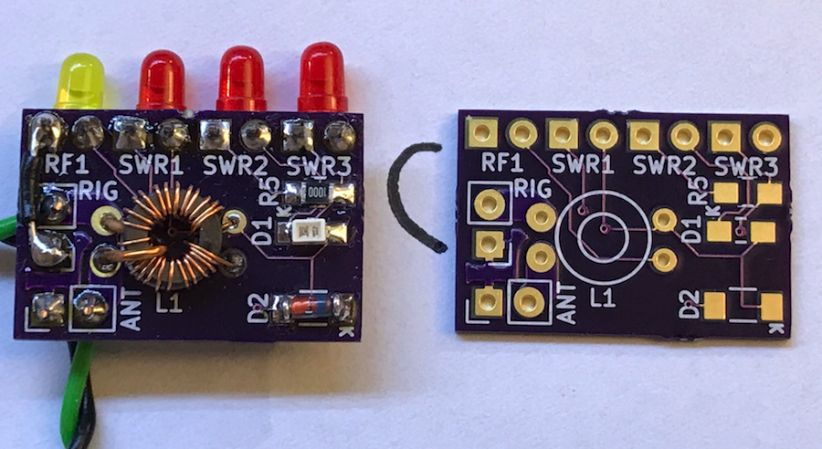
I missed the yellow led and I finally assembled all 4 leds the same: they are red color, Mouser ref. 604-WP710A10LSRD.

Their forward voltage is 1,65V, current 2mA, and are 25 mcd luminous intensity.

According to your comments, I had to swap my connectors, so ANT was used for RIG, and the RIG in the PCB was used for the Antenna.

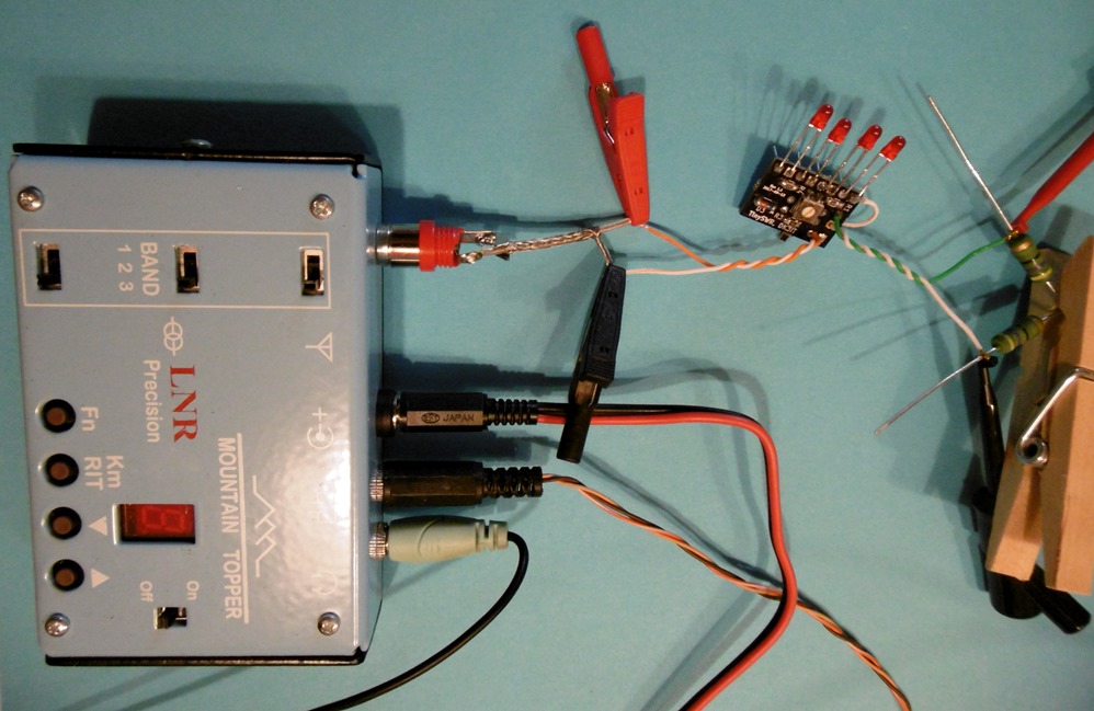
So far I did an initial test with this setup:

  • Rig: MTR-3B
  • Antenna Dummy load: resistor 50 and 100 ohm (SWR 1:1, and 2:1)

First I powered the rig with a 2S Lipo (7,5 Volt), I guess around 2 watt out. I put the 50 ohm load. Key down and the first led light up, all right!

Then switched to 100 ohm and then 3 leds light, being the first the brighter.
I played a bit with the inbuilt potentiometer and got only 2 working, as expected. The second one with little bright. The potentiometer is near its middle position.

I replaced the battery and put a 3S lipo (12V - 5w out). With the same 100 ohm load again 3 leds went on. I adjusted the potentiometer and got only 2 leds working as expected.

REMARK: it is important to isolate every led because the light of every led travels around and it seems the others are lighting!! I used pieces of paper between them for the testing.
Once the PCB is inside a box every led will pass on its own hole, being then well isolated…

PENDING TEST:
I need to repeat the test with some more resistors to fine tune the SWR reading.

Power level is important and affects the brightness and number of leds lightning, therefore I will adjust with 5w that is the normal level I will use with the rig.

Note the clothes peg used to join the 2 resistors of 50 ohm together. I’m running off crocodriles!!

The project is working well. Wishing to have it ready to operate in the box, I’ll let you know more soon.
73 de Ignacio

Dear Ignacio:
Thanks for your great report! I am glad to see that the Open Hardware way of sharing ham radio designs seems to work well!

BTW, the yellow or orange LED for RF1 is not as critical as the red ones.

73 de Martin

PS: When adjusting the trimpot, I recommend to use a position at which the first LED at least glows a tiny bit a a SWR of 1:1.2 or so; this gives you confidence that the circuit works.

Dear all:

Yesterday, I got the boards for the latest revision of the layout (2017-10-24), as now available via OSH Park. I just assembled a new prototype and can confirm it works like a charm. It works best with 2.5 - 5 W, but can be calibrated to also work with 1 W. The only downside of the simple design is that the calibration is accurate only for the same power level (or at least within a narrow power range).

As for winding the toroid, use enameled wire no thicker than 0.22 mm for the secondary winding, otherwise the 25 turns won’t fit well. Make sure you only occupy ca 270 degrees of the core, otherwise directivity might suffer.

When ordering the parts, it may make sense to add a few 100 Ohm / 2 W resistors, for they make for nice dummy loads for various SWR levels.

I hope this tiny SWR indicator will turn out useful for many of you and will save lots of final transistors.

As for the ease of assembly: The board is pretty small and tightly packed with components on both sides. It should not be your first SMD soldering project. But then again, all parts are 0805 sizes and the pads optimized for hand-soldering. Take your time and a good magnifying glass :wink:

73 de Martin, DK3IT

1 Like

Dear Colin, all:

I updated the GitHub project files at

and tried to implement the following issues:

  1. Removed links to unnecessary KiCad libraries.
  2. Improved the assembly instructions.
  3. Added an illustration showing the correct direction of the toroid windings.

The project should now be ready for use.

Any feedback will be very welcome!

73 de Martin, DK3IT