The name is really bad. It’s not no-tune because you need to get the length of wire correct or “tuned” as we say.
You need to measure just what you are seeing or you’ll never know what’s needed to make it better.
Mine used the same ratio (3T : 24T 1 : 8 = 64x impedance transform) and a Polyvaricon on the secondary. I followed AA5TB’s design and tuned mine the same… against a fixed resistor to get the tune point then replace with the radiator wire and trim get lowest SWR without adjusting the capcitor. 5m of radiator worked a dream(*) in that I could have 5m of vertical radiator, matchbox on the ground and a 1m counterpoise wire + 2m of RG58 to the 817. For whatever efficiency it had, I could work most of what I heard on 10/12m with it. Most failures were the problem of busting a pileup with 5W when people were running, shall we say, a bit more power
(*) for whatever definition of dream you want SWR 1blob or less on 10/12/15m and plenty of decent contacts worked (W, VE, PY, etc.). Efficiency? Who knows. There didn’t seem to be RF all over the 817 or mic or key and I could move them about and the SWR was constant.
Thanks Andy. I should have noted that I did attempt to tune the radiator length. Up to a foot in either direction both iterations, and those numbers were the best I could get.
One thing that is dawning on me is that even with a “no tune” setup (which has been tuned before hand) I am going to want at least some way to confirm swr hasn’t changed because of a bad connector, odd deployment etc. Unless I build one of Martin’s swr led boards into the ATS (possible!) that means carrying a little bridge/swr meter at least. And if I do that, I might as well carry one of the tiny tuners with swr indicators (emtech etc). And if I carry a tiny tuner, then I might as well use the tiny end fed wire setup I’ve been using with the kx2.
Today I made two transformers with ft114-43 and connected them back to back and found out that almost half of the power is lost (as heat) indicating almost 1.5dB per transformer.
Of course this was very simple measurement using two power meters and dummy load and it does not tell the real thing at all.
While trying to figure this out and wondering if I my core materials are really what they should be, I ran into this http://w7zoi.net/xfmrsefhw.html
Just wondering if anyone else has measured these famous efhw transformers with diffirent core materials? Oh yes, I know it is only one dB, but thats not the point here.
In the interests of adding some more knowledge to the discussion, Owen Duffy has a series of articles on the subject of EFHW transformers. Here’s his most recent work regarding a transformer identical to the commercial version in question: FT82-43 matching transformer for an EFHW – owenduffy.net
Short answer, the efficiency at 3.5 Mhz for this transformer is calculated to be ~65%. There are also some suggestions on how to begin improving the efficiency. Mr. Duffy also presents a different design for an 80-20m EFHW transformer with <10% core losses in another article: End Fed Half Wave matching transformer – 80-20m – owenduffy.net
Hi Joe, I just built one of these, this weekend. I lost the capacitor that came with it, so used a lower-value one I had. I cut the wire a bit longer than recommended, expecting to trim it down. I threw it up in the back yard, and had around 1.1-1.5:1 SWR across the band (approximately - that’s just the meter on my FT-817). That was direct-feed, no coax.
On my MTR-3B, I use a short (8-inch) RCA-BNC cable. It performs well there, too. To avoid unknown high-SWR situations there, I use the QRPGuys SWR indicator kit.
Thanks Rex. I think the issue I was having was related to an overly short radiator. I haven’t tried it with closer to an actual 1/2 wave length to start.
Btw, thanks for the QSO on Eight Dollar Mt. last week. I recognized your call when I was transcribing logs later that evening.
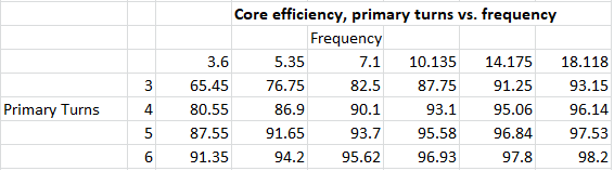
Fleshing out the data a bit, those wanting to experiment with this tuner might use the following chart as a jumping off point. It was derived using the ferrite core inductor calculator, also available on Owen’s website: Calculate ferrite cored inductor (from Al) . Keep in mind that secondary turns would have to be adjusted to maintain the 1:8 turns ratio, and that the capacitance would likely also need to be adjusted. This chart was generated only for the FT82-43 core and should not be used for other sizes or types.
Keep in mind that this will only affect the core losses and that other losses may occur elsewhere in the antenna system.
I don’t have problems using a tuner. I built this one a few years ago and tunes 40-30-20 (my main op bands) just fine. This baby is small and attached directly to the rig. I could have saved a few oz. by not including the LED/SWR indicating circuit since I just tune for peak audio and finish up using the SWR meter on the rig…fast and easy. Set up time is easy too.