World Wide AM activity weekend

Hi Ed,

It is most likely that the DSP settings on transmit are applied to the audio passband before the modulator, so for a double sideband AM transmission, restricting the audio frequency response to 2.5 kHz for example, means the AM bandwidth will be nominally 5 kHz. There is no way I can think of for getting a simple AM modulator to apply different bandwidth to individual side bands. They are naturally occurring mirror images of each other, as we all learned in our fundamental studies to get our radio licences. So to limit the nominal bandwidth of an AM transmission to 2.7 kHz, you would need to limit the audio bandwidth to half that figure. Unfortunately the AM signal would sound very muffled and unclear, because as we all learned in our basic theory classes, voices require frequencies above 1.5 kHz and up to about 2.5 to 3 kHz to give clarity and in practice to provide better penetration of QRM. You can simulate the effect of restricting the upper frequencies from a voice signal using the IF Shift control on most modern radios. The pitch of the voice stays the same but you can cut off the top frequencies or the lower frequencies, depending on which way you turn the IF shift.

So, all that discussion about the bandwidth of AM transmissions refers to double sideband AM, conventional AM. But what some specific radios do is to reinsert some carrier onto a single sideband transmission. If you restricted the audio bandwidth before the modulator to 2.5 kHz then your transmission bandwidth of a single sideband plus carrier would comply with the 2.7 kHz rule.

Finding out how your radio transmits AM is something each operator can do.

And you can even find out without using your manual - use a separate radio in SSB mode tuned to the exact frequency of the radio transmitting AM mode into a dummy load and switch the receiver between the sidebands, USB and LSB. If the LSB signal is clear and strong but the USB signal is weaker and muffled, then the transmitter under test is using single sideband transmission with re-injected carrier. But if the two sidebands sound identical, you know it is transmitting double sideband or conventional AM. This test takes less time to carry out than to describe.

Let’s just hope none of those pesky 5 to 10 kHz wide signals from FT817s and TS2000s and ART13s creep over the border and interfere with the refined narrow 2.7 kHz signals within Germany. (I somehow doubt whether the authorities have really thought this through.)

Each operator needs to satisfy himself that his or her transmission will not interfere with existing users, ie choose a frequency where both USB and LSB are vacant.

I hope that concerns about bandwidth won’t cause more interference than necessary with this very short AM experiment on the coming weekend.

73 Andrew VK1DA/VK2UH

I’ll run the test you describe on both my TS2000 and FT817 over the next couple of days however I believe both of them produce double sideband AM.

Hmm, all these restrictions on Amateurs in Germany, makes the thought of a remote controlled station in the UK very attractive…

73 Ed.

Tests performed (into screened dummy load) - both the TS2000 and FT-817 create AM with both sidebands - so at least 5KHz wide on bandwidth unfortunately.

Ed.

Are you limited to only tranmistting on a single 2.7 KHz wide signal at a time? What if you were to Tx 2 signals at the same time taking up 2.7 x 2 KHz.

Not allowed and I now have my fears confirmed from another knowledgeable source.

Legally AM (or any mode wider than 2.7KHz) CANNOT be used on bands below 10 metres in Germany.

Al Murray was right.

:wink:

Back to activating mountains with AM…

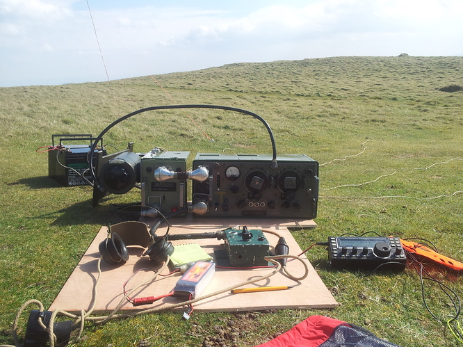
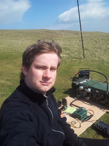
I could have headed out with the KX3 and amplifier today, that isn’t very unusual and thus I thought it would be nice to drag the 19set up again, this time on GW/NW-070, the Great Orme.

I have been experimenting with AM on 60m for the past few months on the mountain tops, I have had some great QSO’s with regular chasers experimenting with the mode and trying new ways to have fun.

Clearly conditions have deteriorated through March, which puts HF enthusiasts in a bad mood !

After last years antics with the Wireless 19 Set, I thought this weekend would be ideal to give it another go. The original day the 02/04 of April proved to be a bad choice. Conditions were in terms of weather and propagation- poor.

Sunday looked slightly better and gave us a chance to experiment with the new Lucas deep cycle batteries on Saturday afternoon, two 34AH’s strapped together to lower the parallel resistance ensures a steady voltage on transmit and it turns out over 3.5 hrs of operator time. Power supply used is the British variant with two separate rotary converters, one on receive the other on transmit. The KX3 was used to spot tune and net the 19set onto its correct frequency. Two pieces of poor quality domestic ply wood came in handy to protect the bottom of the 19set which has been powder coated in its original military colors.

The original 19 Set wire antenna is over 100ft long and can be tuned by joining up three different links. The 19 Set uses a matching device called a vairometer which I like to think of as a variable coupling transformer. Its suitable for matching into high impedance loads and thus on 80m you use less wire then you need on 60m - confusing and
non intuitive but broadband and works for what it was intended for. A four wire shortened counterpoise makes up the other side of the Arial system connected to the radio sets outer can.

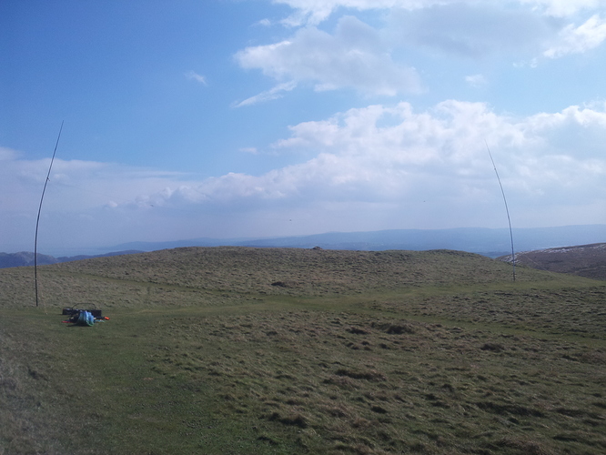
To put up the Arial two poles were used; a 7m at the station end extending up to a 10m setup some distance away the long wire strung up between them. Everything is as it was in the 1940’s apart from the batteries supplying the set and of course the poles, consider it part of the scenery.

We made five contacts. Victor GI4ONL was the most readable and had a good few exchanges with. G8ADD, G4OBK, G4TJC (Using HackGreen as a RX) and G4AZS all made it into the log.

Better conditions would have helped. An improvement in using a custom dipole, removing the vairometer might also improve the efficiency of the arial feed from the tank circuit.

I am expecting to have another go later this year with an emphasis on 5.317 MHz. I am sorry if you couldn’t hear it today. More can be done from this end including using the 19set high power amplifier if necessary, its a very interesting challenge for me at least.

Weather was better then expected which is always a bonus in the UK !

Thanks to all that tried and took part in the chasing. Sorry to Allan GW4VPX chasing, I should have done 60m first. 80m was an obvious damp squib !

Jonathan

8 Likes

Sorry I couldn’t manage a valid 2-way QSO, fighting the Sunday-morning QRM at S9+20dB!

Where to next with the 19 Set? :smile:

Great stuff, Jonathon, you had me punching the air! It’s not often that I make a contact that is so special and so pleasing - it reminds me of Shelley, “Rarely, rarely comest thou, spirit of delight” - and the bonus? I was using the FT817, a nominal 1.5 watts AM carrier, that WS-19 has a decent receiver!

Thanks, mate, you made my day!

Brian

3 Likes

Thanks for the QSO Jonathan. I could hear you on 80m with similar QSB and S/N ratio, but you QSY’d before I felt confident enough to call.

I had assumed that my noise level was local, but while I listened to you, I noticed that the noise level very gently changed between S3 and S5.5 - more slowly than the QSB on your signal. When the two variables were out of phase, a QSO became possible!

It has encouraged me to try a horizontal loop, rather than my general purpose dipole / doublet.

73
Adrian
G4AZS

1 Like

I need another “drive on summit” Thinking NW-064 next ?

I know one of those is done fairly easily by car, trying to remember which !

Still pondering how to get more watts out of this 807 into the Arial :slight_smile:

Jonathan

1 Like

Hi Jonathan,

Great to see your photos and read the story of your exploits with the No.19 set, the whole operation looks so nostalgic. Well done and that certainly captures the essence of the AM mode on ham radio in my memory. What we really needed was a home station running a Panda!

I wasn’t able to activate on Saturday or Sunday but did make a bunch of AM contacts on Friday night. One of the contacts was using a BC348 receiver and an ART13. On Saturday I made a contact with Gerard VK2IO, using my IC736 base rig, then worked Phil VK2ASD whose Tx was driven by “an old Collins 32S1” and had a class E final modulated by a class D modulator… The old mode done in a new way. Interesting contrasts again.

I think the number of AM activators was fairly modest but all have reported enjoying the experience, a good outcome! Thanks to all who participated in any way.

73 Andrew VK1DA/VK2UH

(Currently in Melbourne - came to see Brian Wilson farewell concert)

1 Like

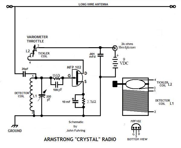
Isn’t the variometer just a variable inductance, created by having the inner moving inductor able to add or subtract inductance to or from the outer inductor. So it’s like a roller inductor in effect. It would be interesting to compare the end fed wire with a simple coax fed dipole.

800v on the 807 would boost the output a bit, might mess with the output design though.

VK1DA/VK2UH

Well a roller inductor behaves like a varying auto-transformer with a sliding tap. The vairometer you are changing the flux coupling between two coils - separate inductors. This depicts it well (not the circuit from the 19set !) :

You can not mess around with the 807 to much because its used as a modulator as well. Any change on the plate impedance by increasing the voltage etc will upset the balance on the audio grid drive. Its a clever set the 19, doing a lot with very little.

It was never designed for long range communications, loading it into short pieces of wire was satisfactory for battle field communications. The best solution will be to match to whats there already with perhaps some added harmonic suppression.

1 Like

Glad to hear you got chased by an ART-13 :slight_smile:

I am awaiting some american nylon stand-off screws for mine as the previous owner decided to mount a 2KV plate capacitor in place with superglue found to my horror last week. The rest of the set is immaculate seemingly !

Thanks for proposing the AM weekend dates. It was very enjoyable from this end.

1 Like

I’ve seen the rotating section connected in series with the main inductor. That way it behaves like a variable inductor.

The 807 might be doing the best it can. Smart circuit really.

Andrew VK1DA/VK2UH

1 Like

Certainly is! The elegance of it’s economy has been a joy to explore. Thanks for taking me there!

Could be an interesting exercise, will be very interested to hear how you implement that.

73 de Paul G4MD

That’s exactly what happens in the 19 set. Except half way round a linked switch changes the connection from series to parallel to give two ranges of inductance for the high and low bands on the radio. Cunning or what :slight_smile:

73 de Paul G4MD

A reminder to all who did use AM on the weekend of 1-3 April to upload their logs. So far the number of contacts logged appears to be low and less than a dozen operators have claimed contacts.

Remember we want to make an impact on the mode statistics for April. Log those contacts!

73
Andrew vk1da vk2uh

I will do my best Andrew, I am behind with logging at the moment. It was a treat to get out to blackpool last weekend !

Jonathan