The 40/30/20m trap EFHW antenna and the coupler shown below were built to match the Mountain Topper MTR-3B in respect of lightweight and simplicity of use.

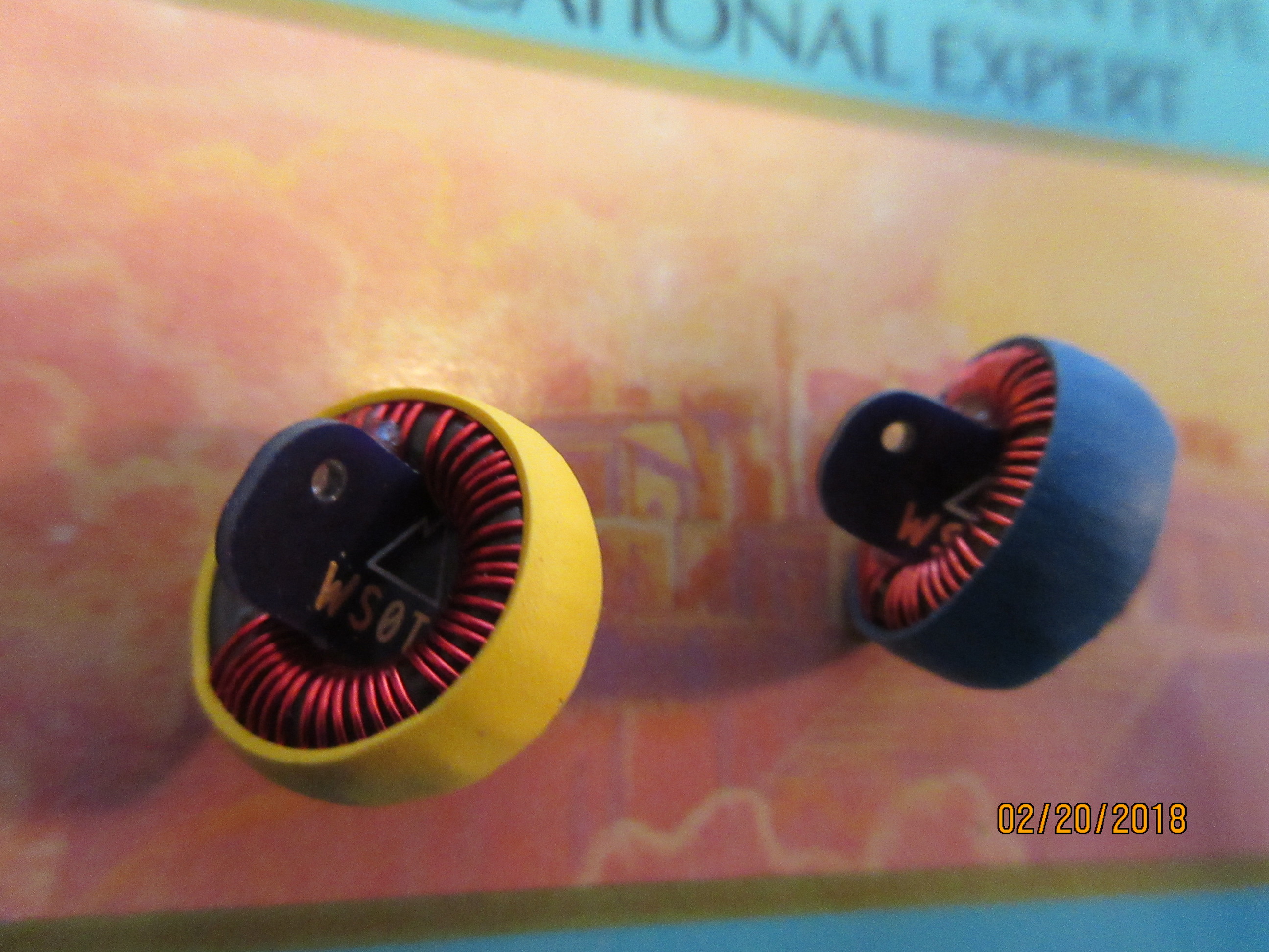
The traps, rated for about 12 W, are built from T44 cores and mica caps, they are protected with shrink tubing with internal adhesive.
The values of L and C are chosen along W1FB such that XC=XL is in the range of 200…250 Ohm.
- 20m: T44-6, 24t #24, mica 50 pF/500 V
- 30m: T44-2, 26t #26, mica 68 pf/500 V
- Wire: POLYS #26 (intermediate section 0.25mm2 RADOX-125, for easier tweaking)


Because I opted for 3200 Ohm as target impedance (like hyendfed.nl does), all my EFHW couplers are built for a 1:64 impedance transformation (LNRprecision has choosen for 4050 Ohm and therefore uses 1:81 couplers, other antenna experts recommend 2500 Ohm).
Nothing mystic about the winding technique, it makes no difference if the winding is applied just straight ahead (as usual) or if it is divided up in 2 halfes. The latter is used for practical reasons to become the input and output wires opposite (what may be wishful at QRO levels…).
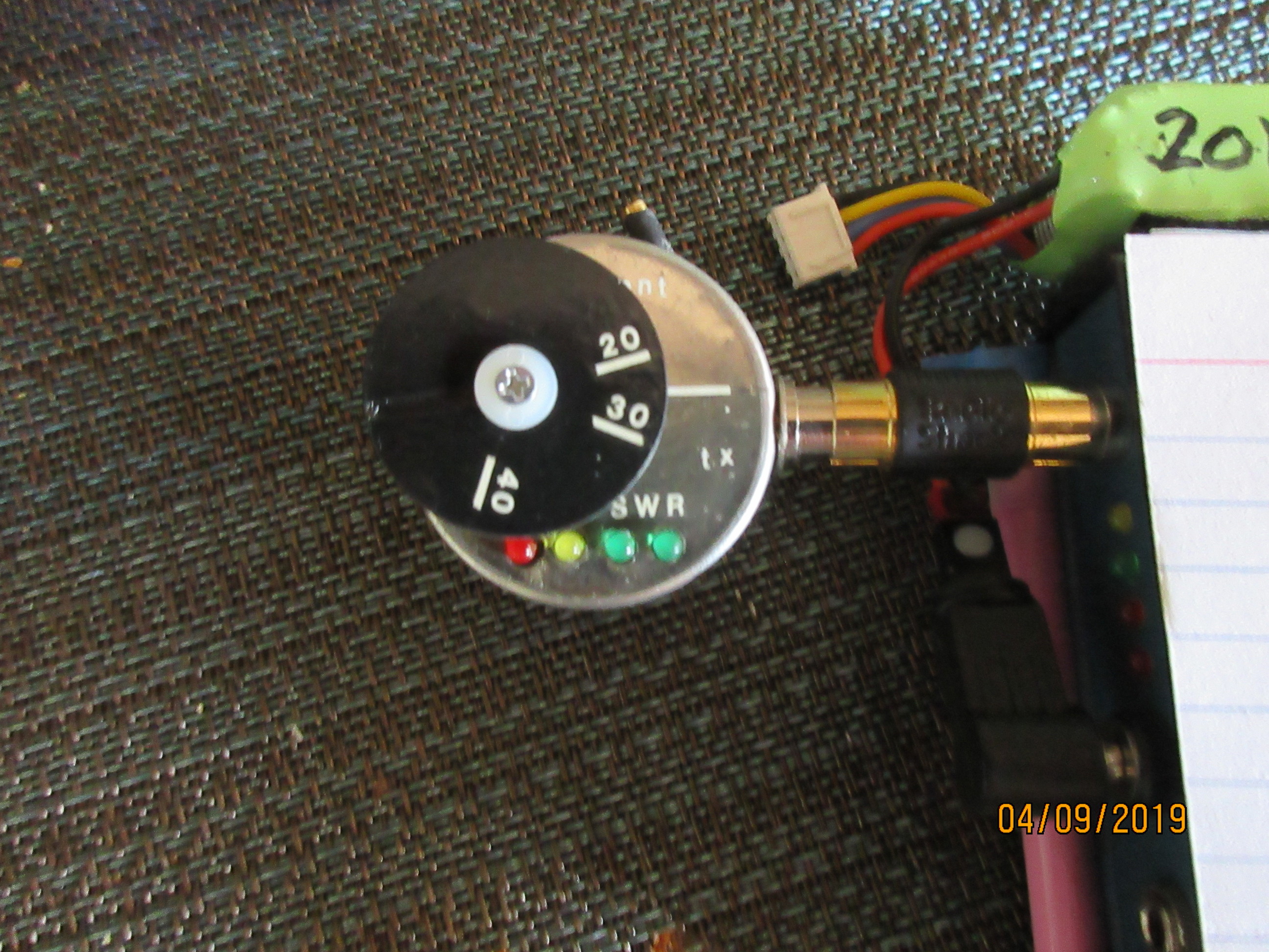
Some of my couplers are equipped with a simple optical RF power indicator (LED). This feature was very helpful last year when a linked EFHW was used (to alert the operator quickly when the band settings at the antenna and TCVR were different…).
- Coupler: FT-82-43, 24t #22 tapped at 3t, mica 150 pF/500 V
- RF indicator: 2 germanium diodes (e.g. 1N34, 1N60), LED red w. transparent body

The couplers are used without a counterpoise wire, either with no feedline or with coax of 0.5, 1.0 or 2m length, depending on the local situation.
BTW, Steve AA5TB modeled a tuned LC circuit (known by the Fuchsantenna) and discussed the findings both from a practical and a more theoretical point of view. Along Steve the modeled 0.05 lambda counterpoise can be substituted in practice by a few pF of capacitance to ground (A/N: that happens „by itself“, without asking the operator, hi). So there is no reason to worry about the "counterpoise question“ of EFHW antennas at lower power levels.
The main features of the 40/30/20m trap EFHW antenna presented above are:
- Resonance frequencies at 7.025, 10.118 and 14.055 MHz
- Total length 16.80m
- Section lengths 9.83, 2.68 and 4.25m
- Total weight incl. coupler, winder and guy rope 132 g
This is now the dream antenna? The answer may be yes and no.
YES, because of it’s simplicity, good efficiency, very light weight, slightly shorter overall length and low wind resistance. The antenna performs very well and has also been successfully used with the KX3 at 10 watt.
NO, because I always believe that you can do something even better, hi.
Well, the slightly lower efficiency of the trap antenna can be accepted because this is in practice hardly noticeable.
Trap EFHW, why not!? Have fun!
Heinz HB9BCB
Addendum of 15.03.2016:
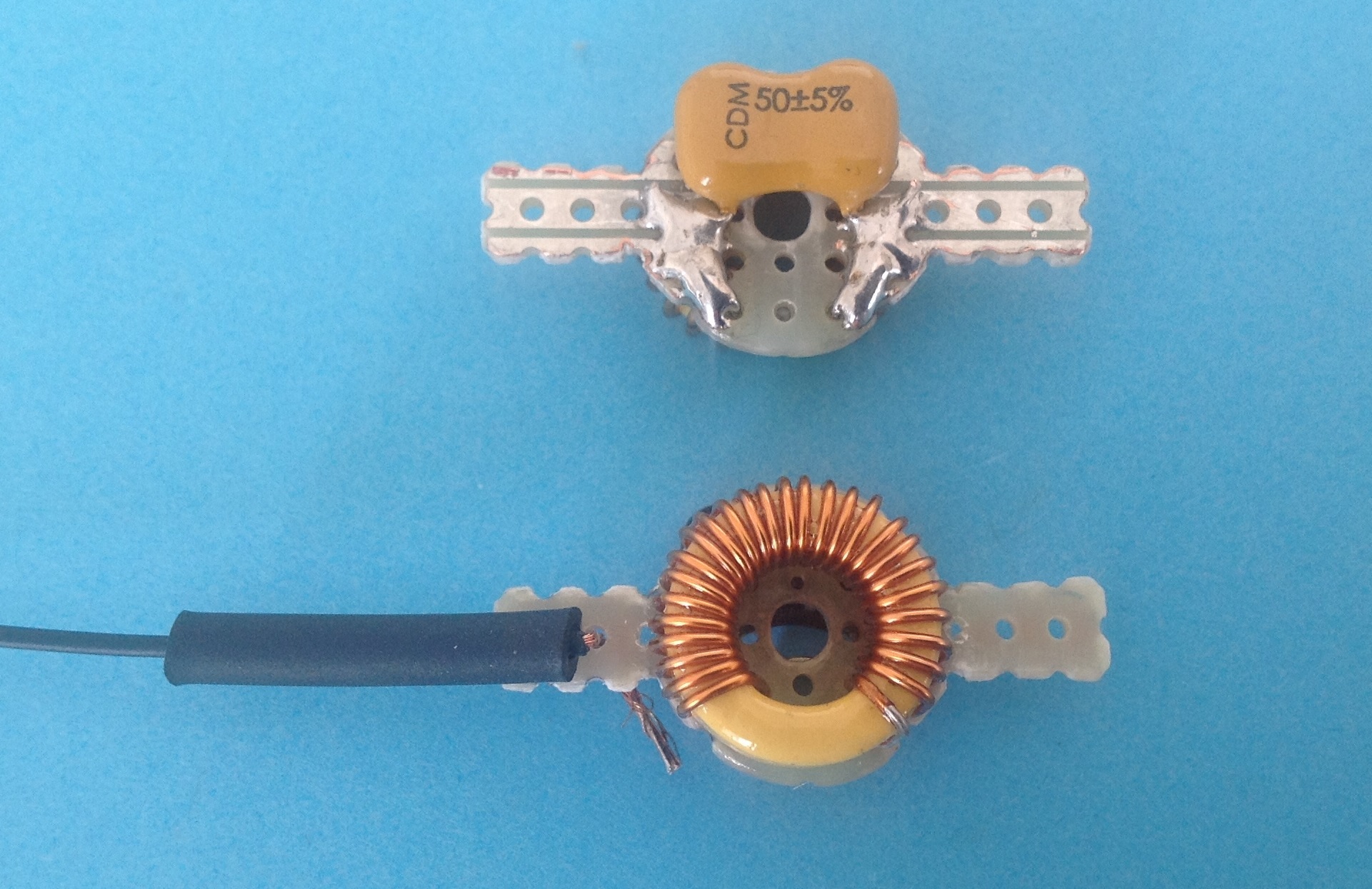
Trap construction details (the photo below shows prototype traps wit T50 cores).
Hints
Windings should be tight, slippery windings will fail.
The hole in the PCB is provided for the 1-turn loop during trap adjustment.
Prevention after adjustment/before heat tube shrinking: any slipping of windings/core on pcb can be prevented with some coats of (transparent) nail polish.