A SOTA diet?
Hi Andy,
So you didn’t do any transmission line calcs? Never mind you can do the sums without your calculator and enjoy Cosh and Tanh without a catenary in sight.
At 18 I could not have bought a calculator at any price. None of the Uni’s had computers although the Department of Defence had one. You must be a young bloke!
It was the upside down triangles that intrigued me.
BTW you posting on the slide show on antennas is very good and partly relevant to this thread.
If an antenna is designed for 6 m height there are a few hard to control things involved. Like ground resistance and whether on flat land a pyramid or a ridge as examples.
Raising the antenna higher won’t stop it working. For example at 7 m not much will have changed. 12 m? The resonant frequency may change for better or worse but the radiation pattern might be better for the propagation at that time.
It should work well with the 5 m highly collapsible “travel poles”.
As Ed has said when you get to a SOTA site the ideal deployment may be impossible.
73
Ron
VK3AFW
Nope, never. My RF work tasks have been the “EMC man” for medical in-vitro equipment and Bluetooth front end processing at the interface between the analog RF stage and the ADC/DAC and the low level signal processing. It’s over 20 years since I stopped doing any hardware design. Everything since has been purely soft.
I don’t know where I found that PDF but it’s useful stuff. Looking again the other day to see if there was an updated version was where I found out the author is now SK.
Going back to the topic - is the centre point height critical (I doubt it) or the angle of the inverted V? I assume the latter, in which case extend the guying extensions off the end of the dipole and peg them further out and raise the centre point - cogruent triangles?
I work to the following. Get it as high a you easily can. Try to have the legs at 60 degrees or less. Try and get the ends of the dipole 1m above the ground. They do still work when just laying on low bushes, just not as well.
Compton
I finally got to try the antenna out yesterday, with miserable results. I am not completely sure what, but I must have done something very wrong while erecting the antenna. The antenna I got is the 20, 30, 40 and 80 meter variant.
The lowest SWR I could see was 2.7 at the 20m band, others were 5+ (and yes, I changed the clips  ). I tried raising the antenna to different elevations, everything between 5 and 9 meters. Anyone got any idea what could be wrong?
I erected this with a rigid support for the mast, and the legs were at approx 180º angle to eachother, could this be the issue?This is how I used my previous inverted vee antenna, so I guessed that would be the case here too.
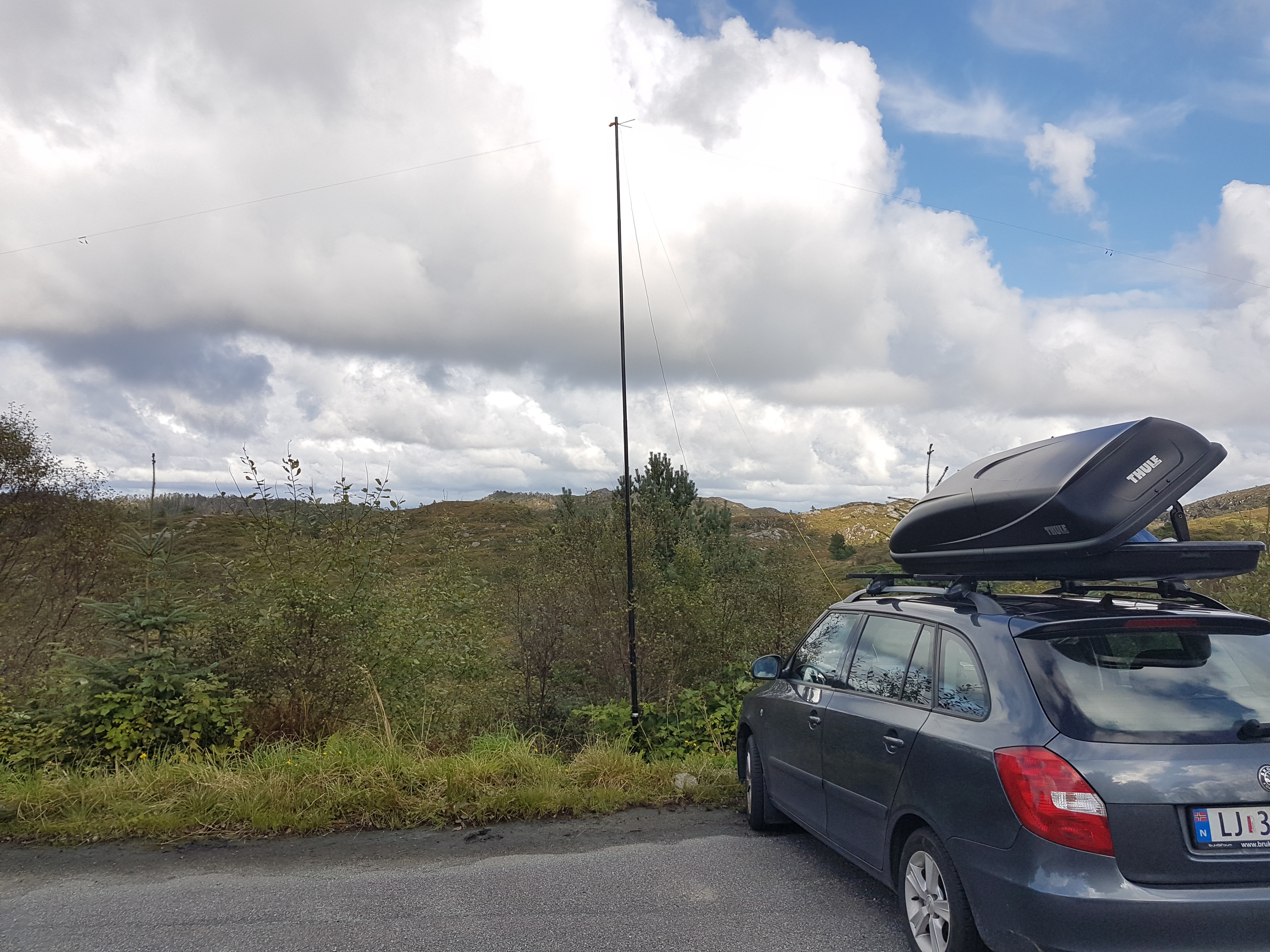
Move the enourmous lump of painted metal away.
2 Likes
Yeah, if that car’s as close as it looks then it probably won’t help…
If it’s been tuned in Vee form, then having it too flat can also cause trouble.
The other thing to do is make sure, where you have open clips, that the inactive (disconnected) end is as far away from the active end as you can sensibly get it. With croc-clips, you can clip it back easily enough.
I’ll give it another try when WX gets better again. Having a car nearby is generally never a problem here, I don’t know of any summits you can drive to in Norway 
1 Like
I presume the mast is not metal - right? Usually a fibreglass fishing pole (aka Squid or Roach pole) is used - using a metal mast could cause all kinds of de-tuning I think.
73 Ed.
Yeah, it’s a fiberglass pole.
When I get that sort of SWR I do a DC test on each leg/section after I get home and dry it off.
73,
Rod
And on the feeder.
1 Like
The antenna is new, so it’s completely dry. I did a DC test on it now. Good insulation between center and shield on the plug (no short), but the resistance from the plug to the end was different. The “shield” leg had approx 2.7 ohms, while the “center” leg had 4.9 ohms. Is this enough to make such a difference? I haven’t done further tests to see if the difference is in the feeder or the legs.
In a word, Yes.
What reading do you get with the meter leads connected together? It should be less than 0.1 ohms. The resistance from either outer or inner of the tx end connector to the other end should be less than 1 ohm. I get concerned if it’s more than 0.5 ohm but then my coax and antenna wire will be different.
It’s not so much that a couple of ohms in a 50 ohm system will make it work badly, it’s to my mind an indication that you have problems on dc and probably worse on rf.
When I’ve had problems like this it has always turned out to be the connectors. I’d start with the TX one. Are you using any adaptors?
The bane of my life is connectors that don’t screw up tight because they are non-standard. That gives fluctuating high SWR.
My Sotabeams link dipole always has an acceptable SWR in spite of a variety of different arrangements in the air. I must go and measure the resistances, just for fun.
Yes the car will have some effect but not 5:1.
73
Ron
VK3AFW
I did some further tests now. First DC with the ends connected together, that came up as around 8 ohms. I then removed the connector (I had replaced it to use one that fit my radio, as I didn’t have a BNC adapter), but I got exactly the same results as yesterdas test with the connector, i.e. that one leg has twice the resistance as the other, one on 2.7 and the other on 4.9 ohms.
All these tests are made with the antennas on the winders, could that be the issue? In which case I still can’t see that it should be such a significant difference.
73 de LB4FH
The shield has more copper in it than the centre conductor. It’s as simple as that. Your DC measurements are about the same as I get on my home made equivalents. I find the layout not to be critical. Every summit is a bit different. There is just no point in worrying about exact height, angles etc.
Martyn M1MAJ
1 Like
Hi,
If for a 40 m dipole the antenna wire is about 0.4 mm dia (copper) and the coax is RG174 or similar thin 50 ohm coax then the resistance from centre to outer of the coax with the antenna ends connected will be about 5 ohms on my calculations. I prefer to use a little heavier gauge wire so my dc resistance check values are lower.
So if seems your antenna is OK in regard to continuity. I initially thought it too high but for light gauge wire it is normal. Good to have some reference values.
So can you confirm your apex was at 6 m. Impedance varies with height.
Can you confirm the ends were supported by the supplied ropes and the end pegs were on about the same horizontal plane. The included angle between the wires is more important than whether they are in a straight line.
The feedline of course should come down the mast and therefore be symmetrical with the radiator… It doesn’t have to be perfect but if it were to be run close to one radiator the results would show up on the SWR…
Do you have an impedance analyser? If so you can measure the antenna parameters outside as well as inside the band to see where the apparent resonance is - no reactive component - and where the minimum SWR is. You are at the end of I guess 7 m length of coax so the values you measure will be a bit different at the feedpoint but at the end of the day you want a low VSWR at the coax connector.
Your SWR meter might not be accurate. Check it with a 47 ohm and a 220 ohm resistor.
My experience with this manufacturer has been SWR less than 2:1 on an 80/40/30/20 link dipole. 5:1 isn’t acceptable but if all the above checks our OK I’m out of ideas.
Of course Compton has a point, backing the car off can only help.
73
Ron
VK3AFW
I have had the wire crack inside the insulation. This gives an intermittent fault; often OK when slack and broken when taut and thus hard to find.
Good luck,
73,
Rod
Edit : Kevlar reinforced wire seems prone to this; the wire snaps but the kevlar stops it stretching and breaking the insulated cover too.
2 Likes
I should just do another test at a more suitable location, with no cars nearby (there were also other cars parked next to mine). This was the only available area for my at that time, but I might find a better spot this weekend.
I tried various apexes, from 5 to 9 meters. The best results were at around 6-6.5 meters or thereabouts (no exact measurement), so that should be acceptable according to the specs. The legs went out to the same vertical height, attached at the end of the ropes. The feedline was near vertical at the 6m test, but as you see on the photo it slopes out a bit more at the higher elevations.
I checked with the built-in SWR graph on my Xiegu X108G, I haven’t seen major differences between this and a “normal” swr meter while testing, certainly not on this scale.
Thanks for the hints and feedback, I’ll do another test and come back with the results ![]()
Hi lb4fh.
This perhaps a bit off the topic of the original post in this thread, but relevant to your high SWR problems. I had problems like yours with a SotaBeams Bandhopper antenna (20/30/40m) and my 817ND. The antenna was brand new out of the box, but disappointingly, mostly no signal out, very high SWR on all the antenna bands (with the links open as appropriate).
Detailed tests with an antenna analyser (RigExpert) and resistance measurements suggested that there was a fault/problem located where the output of the balun attaches to the two legs of the dipole. This was under/in the hot-melt glue on the top orange plastic plate - hence inaccessible.
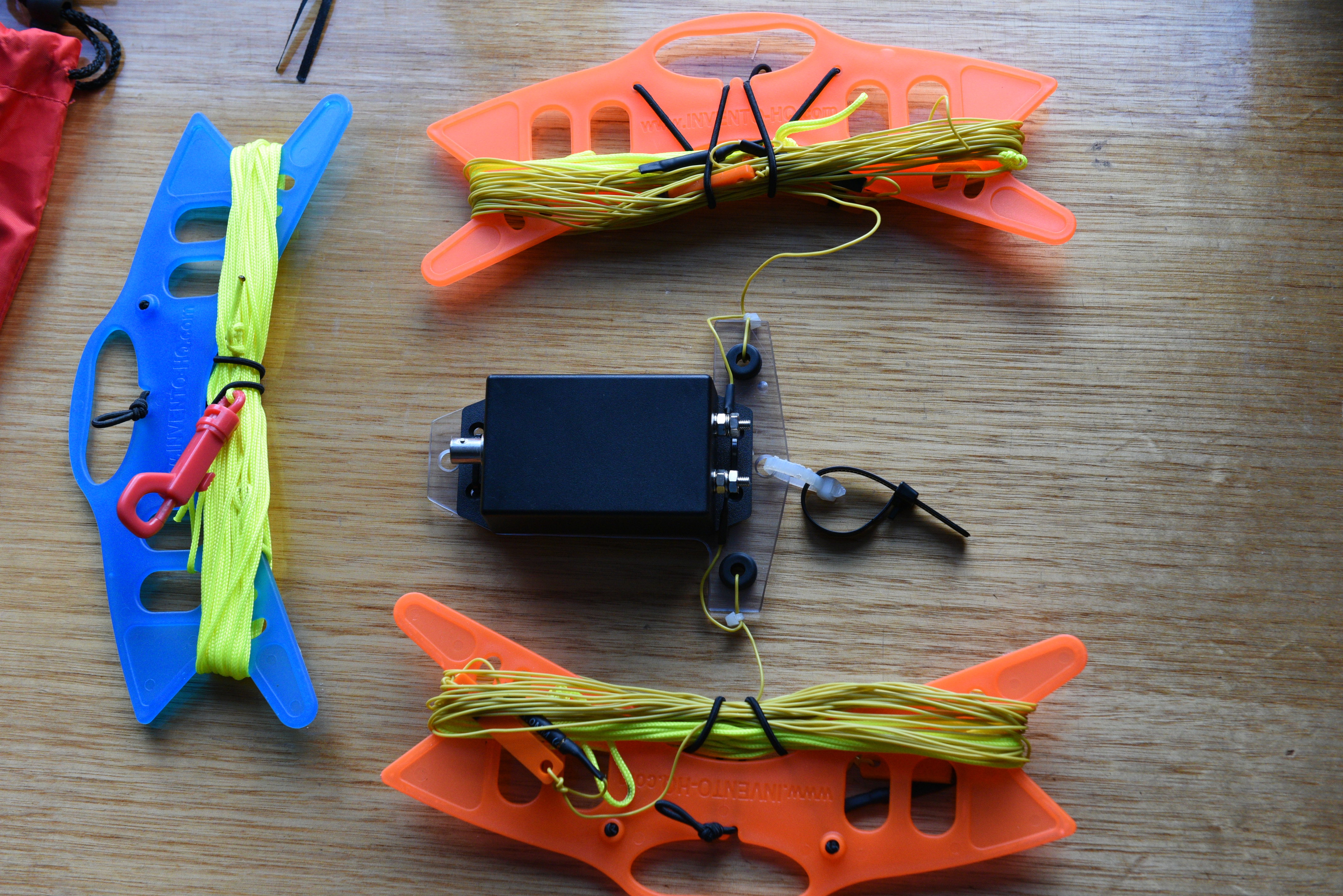
I modifed the antenna as shown in the following photo:
- the orange plastic mounting plate was removed competely - all wires attached to this plate were disconnected
- the balun was mounted in a small plastic jiffy box, with a BNC input and two screw terminals for the output (centre conductor and outer braid). This was then attached to a home-made plastic T piece with cable ties
- tags were soldered on to the ends of the dipole legs to attach to the balun output
- the trusty-rusty croc clips for the links were replaced with gold-plated bullet connectors and sockets
This antenna now works very, very well on 20, 30 and 40m and is very forgiving of variations in mounting height, alignment of the dipole limbs and so on - just as Mr SotaBeams intended. As modified, each component is accessible for stand-alone testing if something goes awry.
If you decide to go down this path you can use whatever coax / connector you like for the feeder, but it is best to attach this to the mast just below the balun and make the connection with a loop that does not put a lot of strain on the BNC. I use reusable cable ties to attach the T piece and feeder coax to the mast.
I hope this helps. 73
Leigh VK3SG
1 Like