The inserted coil has two different functions.
At 7Mhz it acts as an extension coil, the well-known principle.
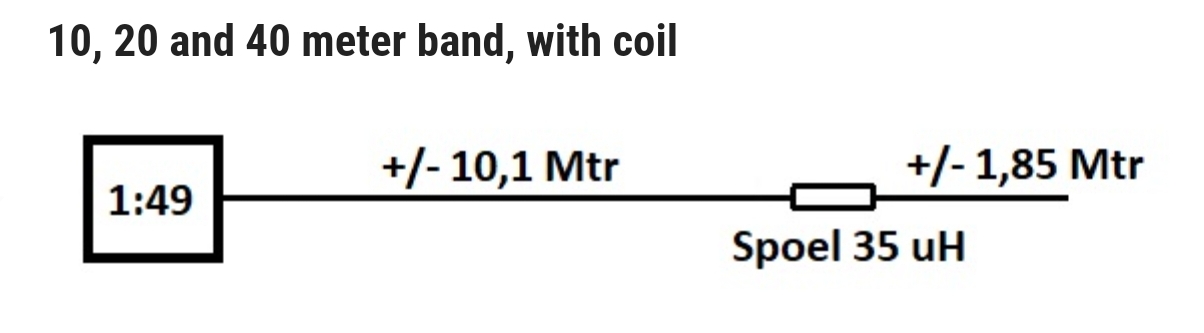
At 14Mhz it acts as a resonant circuit, a trap.
What is special about this trap is that the capacitance is provided by the wire ends and coil winding. There is a detailed calculation formula from OE5CWL/OE6CWL for the inductance that achieves the correct shortening factor for 7Mhz and the resonant frequency (14Mhz). The wire length to the right of the trap plays an important role here.
The inserted coil has two different functions.
At 7Mhz it acts as an extension coil, the well-known principle.
At 14Mhz it acts as a resonant circuit, a trap. What is special about this trap? The capacitance is provided by the wire ends and coil winding.
There is a detailed calculation formula from OE5CWL/OE6CWL for the inductance that achieves the correct shortening factor for 7Mhz and the resonant frequency (14Mhz). The wire length to the right of the trap plays an important role here.
EDIT
OE6CWL called these traps CWL traps and used them with dipoles. PA3HHO now had the idea of using these CWL traps for end-fed antennas and presented the 1:64 transformer.
EDIT
i have an excel file to calculate. With this I was able to successfully calculate antennas for 20/15m and 20/10m. 60/40/20/10m or 30/20/10m would also be conceivable, with the extension coil working for 60m or 30m
73 Chris