Seven SOTA antennas compared using WSPR on a summit

The arrangement of the referenced antenna was as follows:

  • Antenna wire of 9.20 m vertically at the GFK mast
  • Feed point approx. 10 cm over ground, directly connected to the TRX/ATU (without coaxial cable)
  • Radial wire of 5.1 m lying on the ground (reasonably flat meadow)

Note
This antenna (without an impedance transformer) also has advantages in addition to the obvious disadvantages:

No reflection loss due to mismatch at the impedance transformer input.
These losses lie at an approximately 10 m long antenna wire and a 9:1 (450:50 ohms) impedance transformer on the 20 m band in the range of approx. 50-60%

BTW, The transmission losses of a well-built impedance transformer are insignificantly small compared to the reflection losses due to mismatch on the transformer input (frequency dependent) and therefore negligible.

2 Likes

A couple of comments Ariel.

  1. I feed my EARCHI with RG-58, 12ft maximum length. I would never use RG174.
  2. I’m more interested in NORCAL doublet fed with twisted pair salvaged from CAT5e (teflon insulation). Super lightweight, super inexpensive. I notice in a recent posting that N6AN uses this.

I hope one day in the future to conduct my own antenna tests using WSPR, but it will be a while.

73, Barry N1EU

Are you sure about that? Speaker cable as RF transmission line – owenduffy.net

1 Like

Richard, NY4G is talking of 300-ohm twin lead, not speaker cable which your linked article measures. Also the linked article’s calculations are for resonant dipole and not NY4G’s non-resonant 44ft doublet.

73, Barry N1EU

1 Like

Thanks. I thought the Norcal doublet was an antenna made entirely of multi core cable. Clearly I’m wrong.

1 Like

No, you’re not wrong Richard! That being said, the term “NorCal Doublet” is sometimes used in a less strict sense to mean a 44ft doublet fed with a variety of balanced feedlines. Especially since, as you astutely pointed out, speaker cable is a lossy feedline.

73, Barry N1EU

1 Like

The original Norcal Doublet used ribbon cable, which isn’t as common these days. Today, Cat 5 cable might be an option. The antenna is a 44 foot non-resonant doublet.

A zip cord dipole is different. A QST article measured zip cord as 105 Ω feed line with a matched loss of 4 dB per 100 feet at 14 MHz. 105 Ω isn’t a terrible match to a resonant dipole, but losses could add up. Here is the QST article from March 1979.

http://www.w1npp.org/events/2010/2010-f~1/antennas/wire/790303~1.PDF

So, different antennas made with different wire. Non-resonant vs resonant and computer cable vs AC (mains) power cord.

wunder

1 Like

I experimented with the big brother 88ft doublet as a SOTA antenna some years ago. It was a fair antenna and its rolled up ready to go again. I used surplus #24 Teflon twisted pair, with stranded conductor. Quite tough and good at low temperatures. Untwisted the two wires to make the doublet, so a one piece antenna. Similar to this stuff https://ebay.us/iWKTxz

My notebook says I settled on 2 x 13.4m top with 8.35m of feedline, didn’t use balun. On most summits the KX2 internal ATU would find a match 60m through to 10m. The feedline length and VF dictates your impedance at the ATU, so 8.35m was not a random length. I imagine 8.35m feedline would work on the half size 44 footer also, but you would need to experiment. Its a bit short for 40m so you may struggle to get a match.

Sorry for the mad mix of imperial & metric :slight_smile:

73 Gavin
GM0GAV

1 Like

Richard

After reading the blog article - I take back the term loss less (implying no loss). I was more implying less loss compared to a lossy coaxial feedline. Owen Duffy’s article makes me pause at that conclusion as well. Thanks for the comment though - you have a valid point.

I just tested the VSWR and the mismatch on 20m at 15:1 maybe too much for some tuners.- losses notwithstanding.

Ariel NY4G

Barry I used 4 conductor computer cable - not twin lead. This is as in the original NORCAL article. I am not sure whether anyone has done a loss measurement on 4 conductor computer cable. I am planning to do a back to back WSPR test with one of my end fed half wave transformers.

Ariel NY4G

1 Like

Appreciate the discussion. One interesting point about the 44ft length. Any longer than 44ft, and it will no longer feature a bi-lobed broadside radiation pattern on 10M. The same will be true for the 88ft doublet and 20M.

I’m interested in how CAT5e twisted pair (teflon/stranded) feedline loss would compare with 300-ohm twinlead feedline loss for the SWR’s encountered on 40-10M with the 44ft doublet.

My goal is a simple efficient dx-capable multi-band antenna to be used with ATU

73, Barry N1EU

The original article says a 28ft feedline for the 44ft NorCal. Converting that to real dimensions gives 8.5344m.

Looking at the tables at the end of this spec, it appears that the insertion loss of 100 m of Cat5e at 16 MHz is 8.2 dB. For Cat6, that is 7 dB. But I just skimmed it.

wunder

1 Like

8.2dB loss/100m for CAT5e would be 0.66dB for 8m feedline which would be fine. (there are also SWR losses for the feedline)

Barry,

the 28ft feedline is significant, it avoids the voltage peaks at the input to the ATU. It may have been a lucky find by the original designer, but I suspect not. If we know the VF of the flat data cable originally used we could check that out.

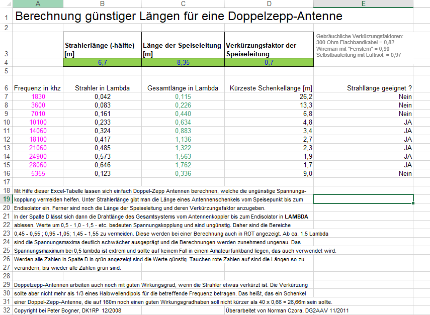
My 8.35m (~27.5ft) was calculated with my best guess of the VF of PTFE twisted pair being 0.7. There has been lots of work done on this by DL’s over the years, including spreadsheets and programs for calculating the lengths to use / avoid for multiband. I have a spreadsheet in German, but cant find a download link to it now. Today’s German test is attached!

Perhaps a native German speaker like Heinz HB9BCB will be able to add a bit more. But the feedline electrical length is important, even to the extent of accounting for the transmission line length in your balun!

73 Gavin
GM0GAV

1 Like

The link:

Yes. The antenna must always be considered as a whole here together with the feed line.

With the help of this Excel spreadsheet, it is easy to calculate double-Zepp antennas, which help to avoid the unfavourable voltage coupling.
Under radiator length you enter the length of an antenna limb from the feeding point to the
to the end insulator. Furthermore, the length of the feed line and its shortening factor must be entered.
In column C, the wire length of the entire system from the antenna coupler to the end insulator in LAMBDA can be read. Values around 0.5 - 1.0 - 1.5 - etc. mean voltage coupling and are unfavourable. Therefore the ranges 0.45 - 0.55 ; 0.95 -1.05; 1.45 - 1.55 should be avoided. These are also displayed in RED during a calculation. From approx. 1.5 lambda the stress maxima are clearly less pronounced and the calculations become increasingly inaccurate. The voltage maximum at 0.5 lambda is extreme and should in no case be in an amateur radio band that is also used.
If all numbers in column C are displayed in green, the values are favourable. If red numbers appear, the lengths should be changed until all numbers are green again.

Double-zepp antennas still work with good efficiency when the radiator is slightly shortened. The shortening should not be more than 1/3 of a half-wave dipole for the frequency in question. This means that one limb of a double-zepp-antenna, which should still have a good efficiency on 160m, should not be shorter than 40 x 0.66 = 26.66m.

73 Armin

3 Likes

I believe that the 44 ft doublet as a system may have come from the work of LB Cebik W4RNL. He did a lot of work on this. A summary is here. http://www.n5dux.com/ham/files/pdf/W4RNL%20-%20Top%20Five%20Backyard%20Multi-Band%20Wire%20HF%20Antennas.pdf

More here: The All-Band Doublet

And here: Only One Wire

The NORCAL doublet was suggested by Doug Hendricks - KI6DS

2 Likes

The red and green number display is in column C, not column D. I believe it’s the column C numbers that must avoid multiples of 0.5, correct?

For CAT5e velocity factor of 0.64, feedline lengths of 7.6-7.8m are favorable.

Thanks & 73,
Barry N1EU

Hey Barry

of course you are right. I have corrected it.
The total length of the system (radiator and feeder) should not be a multiple of 0.5 lambda.

73 Armin

1 Like

Armin,

thanks for finding the original spreadsheet and the translation, that’s excellent. Hopefully it will help people find a good feedline length for their doublet.

73 Gavin
GM0GAV

2 Likes