Maybe its the same thing like described here (second balun). When using symmetrical feeding lines there are similar effects with common mode currents. When the feeder acts as a radiator (coomon mode current) the situation around the feeder affects the SWR.
Well, I was already confused about this. How can I know how many ohms are in my antenna or feed line? I know ohms are a measure of resistance, and also impedance (? here’s where I’m a bit fuzzy on the concept) and I know how to measure ohms through a resistor but I don’t know how to measure the ohms in/at a feed line. So, how can I know whether I need 2:1 or 1.5:1 or 4:1 or whatever?
As expected everyone has given their $0.02 and confused the pants off you.
There are 2 kinds of half wave dipoles… centre fed and end fed. Centre fed is easiest as it 2 lengths of wire and some coax. Its impedance will be sort-of right for your radio. You can make some kind of balun and see if it makes a noticeable change. For QRP HF SOTA, RG-174 is more than good enough coax and just about any old thin wire will do.
An end-fed is exactly the same apart from it’s fed at the end and you need some gubbins (inductor/capacitor) to match the antenna’s impedance. It works the same. But if you’re a noob then it’s harder to make as you have to make (not buy, make) the match unit. It’s not hard but play with a centre fed first. Learn how it works. Then make your endfed. See how it works the same but can be rigged into the air differently. Play with it.
When you have made a few you can get adventurous and try verticals and multi band and … and … and… all sorts of magical stuff.
Make a coax centre fed first as it is the most likely to work first time. Do you need a balun, theory says yes. Practice says maybe. So make a balun out of 5-10turns of the coax feeder. You can see if it makes a difference or not.
The make an end-fed and play with different match units. Walk then run. Then you can try balanced feed instead of coax. There is lifetime’s worth of fun to be had playing with simple bits of wire.
Just remember no antenna is perfect. But any antenna is better than no antenna.
They have wandered off topic. It’s congenital. Your sympathy and forbearance are appreciated.
A straight dipole, way up in the air is 70 ohms. It just is.
An inverted V dipole, which is how you are going to pitch it on one pole, is closer to 50 ohms, so you are not wanting an impedance transformation.
You want a simple (1:1) current choke balun i.e. you wrap the transmission line through a ferrite core 5 times or more. There are some nice pictures above.
It doesn’t need a box - ferrite doesn’t rust.
Just to be clear. 5 turns of coax through a ferrite ring/sleeve is a balun.
5 turns of coax in air, is not** a balun at 40m (but it is at VHF eg 146MHz)
** Ok, so I just asserted that, and thought I would check. 5 turns on 100mm diameter = 4.5uH → XL@ 7MHz=198 ohms. This would reduce the current down the outside of the coax to 1/4. That would be enough to reduce the effect on antenna pattern significantly. The radio would still be “hot” - which only really matters at high power. Any switchmode/computer noise at the radio would be almost unaffected by this.
So it would likely be useful in the field (better than not doing it), and a very poor choice for home station.
Great discussion. I do have an EFHW that i made at home for my 100W base station, but by “dipole” in this thread I’m specifically asking about the center-fed type. (I guess all antennas are dipoles, technically.) I do have a bit of experience with soldering and kits, and have wound a few toroids, but I don’t have the electrical knowledge to design my own.
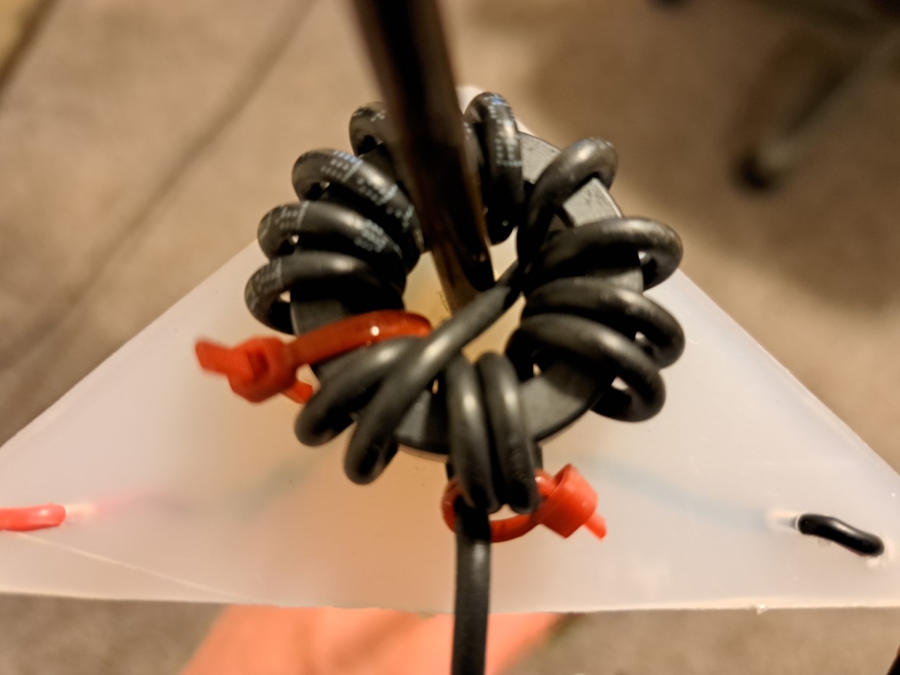
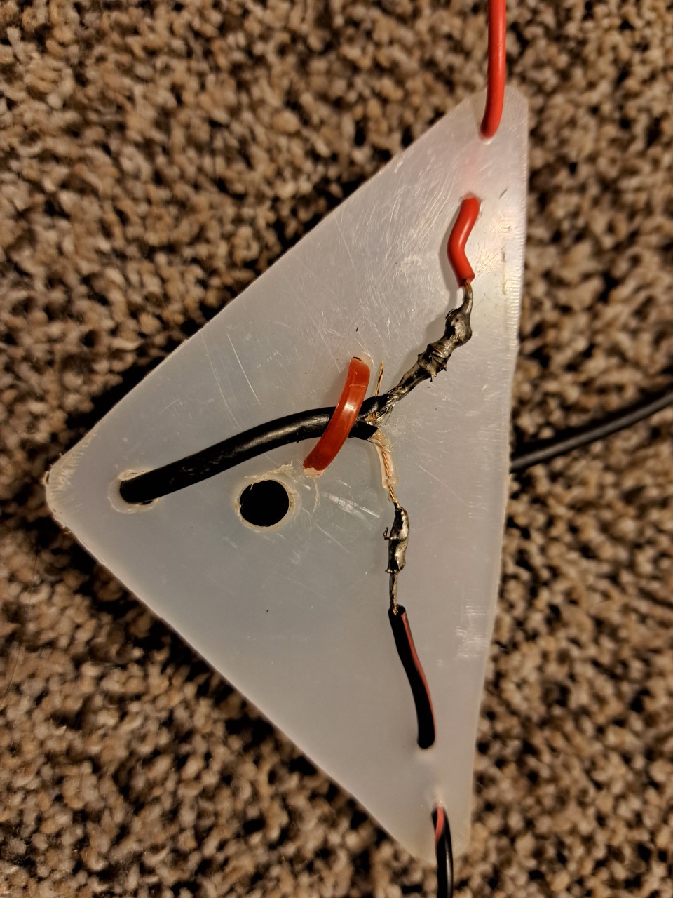
I made a linked dipole for the 40,20,15 and 10 meter bands, but you could do whatever bands you wanted. I used rg-174 for the coax, wound that around a 114-43 ferrite. Attracted the ferrite to a piece of plastic, with a hole in the center for a mast. I used thin speaker wire for the dipole legs, and Anderson powerpole connectors for the dipole links.
Hi Joseph,
you may want to have a look at How to Build and Tune a Linked Dipole Antenna.
Charly, NJ7V has explained everything in detail. The construction is pretty easy and you can add a choke if you would like to and also design the links for other bands. The calculator on the SOTA maps page gives more than sufficient extra lenght for the connectors.
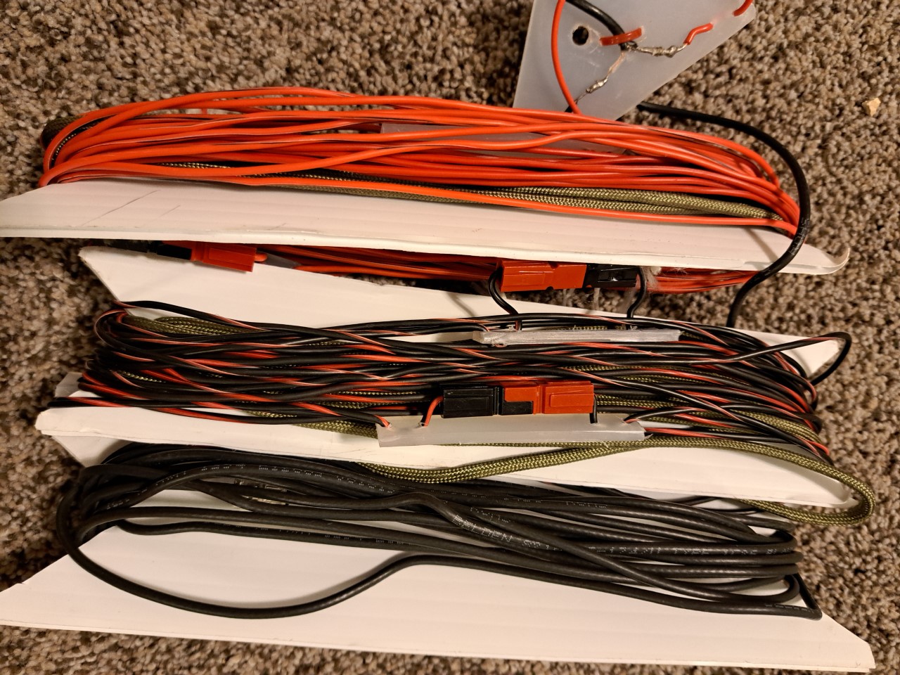
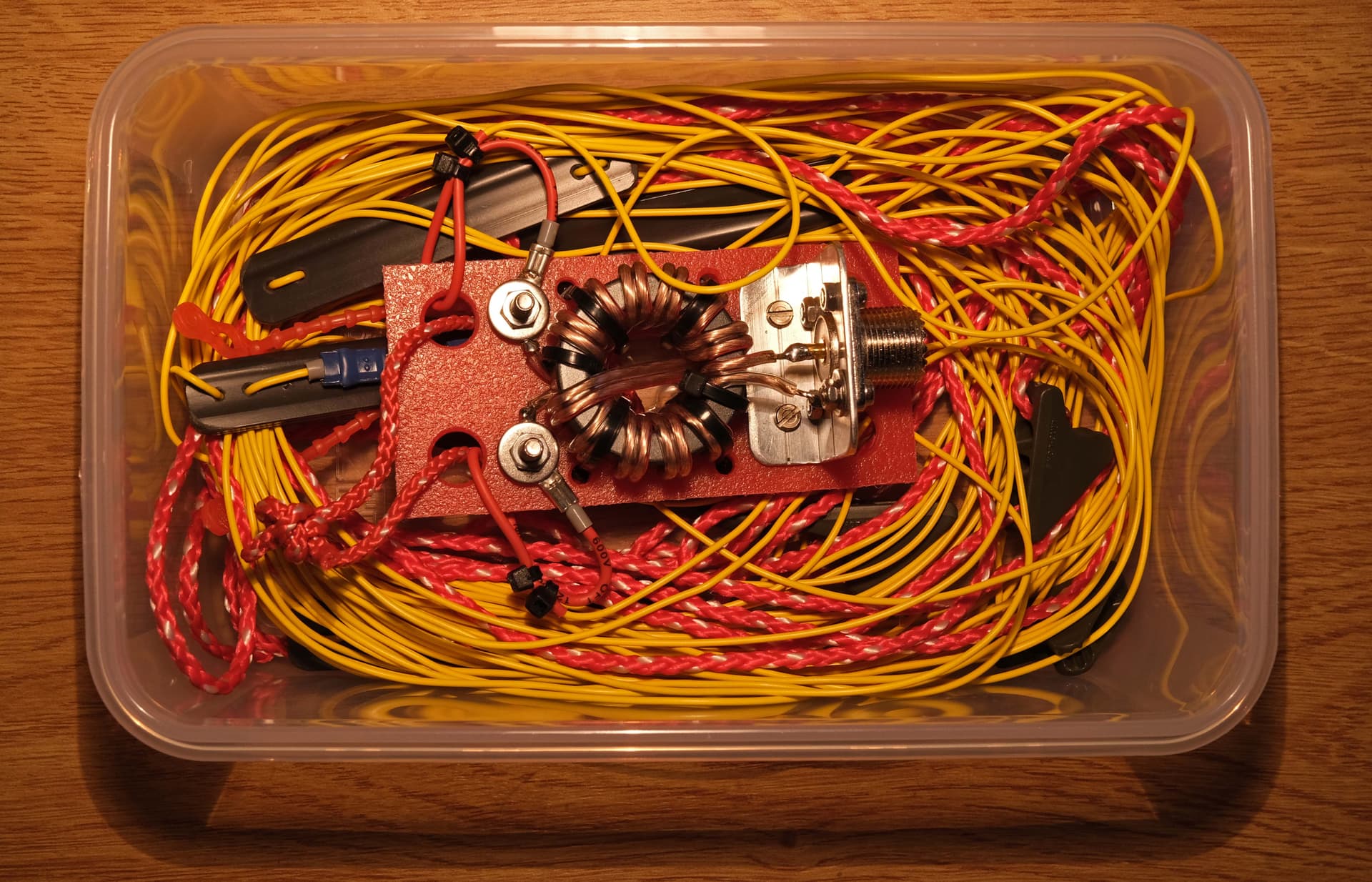
My version of the linked dipole is definitely not optimized regarding weight but fits easily into a small box.
In the past I used the “guess 'n trim” approach like NJ7V, but you are walking back and forth, it is too slow when you need to trim on a summit, and it is hard to trim a multiband antenna like an EFHW or a 40/15 dipole for multiple bands and get it right.
I changed to calculating the required changes. It is faster and easier - even easier when you use a programmable calculator (HP42 on my phone)
Method
Tie your wire to the guy strings 2m from the end. (i.e short). This lets you make easy adjustments without changing any knots.
Strip the end of the wire 1"
Pull the wire out along the guy string, and twist the bare end around to hold it in place along the guy string.
Find the frequency of lowest SWR. If you have an antenna tester or vna this is trivial.
If using the swr meter on a rig e.g FT817, the low point is wide and flat and hard to see, so you do this by finding two equal SWR points either side of the low point eg at swr=3, and splitting the difference. You need to open your rig up as you will likely need to transmit out of band. Set to lowest TX power.
eg swr=3 at 13.7 and 14.2 → Fmin= (13.5+14.0)/2= 13.75
Now the wire is roughly 1/4wave ie L= 300/ F /4 = 75/F
Decide what frequency you are tuning for e.g 14.3.
Calculate the desired length: Ldesired= 75/14.3 = 5.25m (store this)
Calculate actual length: Lactual = 75/13.75 = 5.45m
Difference dL= 5.25 - 5.45 = -0.21m
The actual frequency is lower, so the wire is too long, so we will shorten the wire.
Roll up 0.21m tightly round your fingers, and tie it to the guy with wire/twist tie/velco, whatever. Don’t leave it dangling.
Repeat if needed.
For EFHW antenna, L = 150/F (not 75)
If you are trying to adjust for multiple bands e.g 40m and 15m on a 40m dipole, then measure both bands, calculate both length changes, and decide how much change to make. Note that you still calculate the same, even if the antenna is 3/4 wave long, dL will be the same.
The higher frequency will be the most sensitive, so you are mostly adjusting for that, and your first trim should be to try and get the higher one.
Simple, go straight to Extras - various tools for SOTA purposes - sotamaps.org You may need to make some adjustments but it is very accurated.
There are tons of videos on youtube and you can pick some good ideas from them.
Balun? Yes, because with it the memory keyer doesn’t go crazy, the noise level is less, any summit that I activate the dipole always stays in the same parameters as when I built it.
Good Luck and 73
I do not know why the calculation method you describe does not show up in the first run when using the SOTA maps extra calculator. However, once you have entered the desired bands and performed the calculation, you can export a pdf file that contains all data and also a detailed explanation of how to shorten the wires depending on the measured resonance frequency and target frequency [exactly what you described as well]. I have used the formulas and can confirm that they give a very good indication. The precision seems to be dependent on how far you are away with your first shot from the target frequency. I did the shortening with a bit less than advised and “iteratively”. This way, the reduction in “snip-and-measure cycles” can be significant.
Anyhow, an easy and good exercise, a lot of fun and satisfaction with a well working antenna at the end.
I was building a new (lighter than my older one) 5-band linked dipole back in September, and took it up a local hill where it’s nice and quiet to cut and tune the sections. It was obvious to me before I went up the hill that I’d need a better method than just “cut some off each section in turn and see how it turns out” in order not to spend days up there.
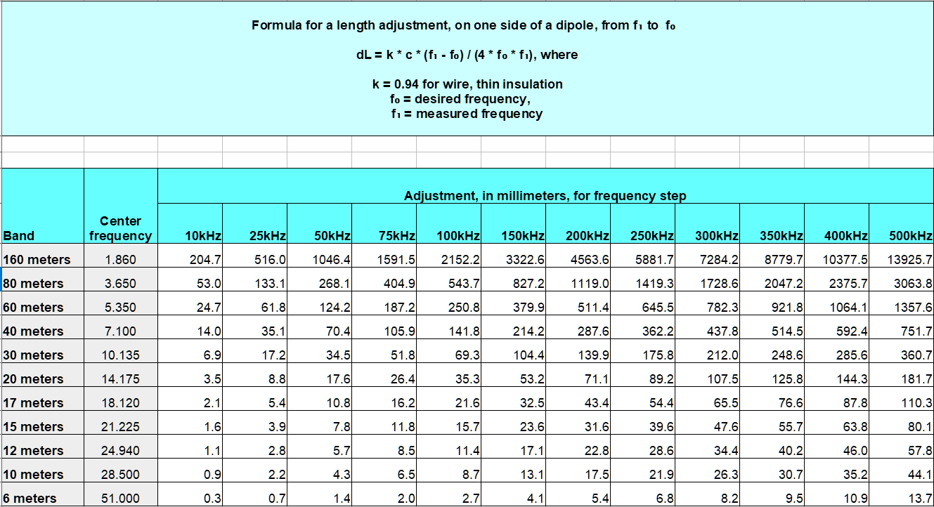
OK, the PDF export from the sotamaps antenna designer does give a pretty fair description of how much to cut off to achieve a desired shift in frequency, but I wanted a perhaps slightly handier way for outdoors of estimating the “right” amount to cut in one shot. So I came up with this spreadsheet, printed it and put it in a plastic folder so I could just scan the numbers easily without having to do any calculations “on the hill”. It’s easy to do a rough addition of two values to get very close to the amount to cut to achieve resonance at the desired frequency:
Ideally, I should have included a field somewhere to enter a shortening factor for the type of wire, and which would be included in the formula used in each cell instead of the hard-coded 0.94 value - but I was too lazy to do that.
Printed out, it might prove useful to others; alternatively it could be an incentive to others to come up with their own version.
Hi Ron,
Is it not amazing that most useful inventions have already been made by others before?
There is a table available from DL2LTO. It is in German, but somehow selfexplanatory. It lists the required change in length per 100 kHz frequency shift.
Yes, Peter, that is a nice table there from DL2LTO. I don’t know about you though, but I personally find the mental gymnastics of multiplying by, say, 2.3 to get a 230kHz difference in resonance to be too much for this old brain while trying to manage all the other stuff needed to get an antenna tuned in the field. That’s why I decided to make the above table which requires only addition.
So, a 230kHz change at, say, 40 meters would be got from the figures in my table for 200kHz and 25kHz, with a little mental rounding up or down, so 287.6 + 35.1 is roughly 290 + 30 = 320mm to cut - maybe 325 - within a couple of millimeters. It’s the KISS principle.
Using DL2LTO’s chart (as does the table in the sotamaps designer PDF export file) would require me to multiply: 2.3 * 1.4cm ≈ 28 + 4.2 = 32.2 or 322mm, which I could do when fresh, but after a couple of hours? Not so sure - anything distracting me from getting it right is one more source of potential error - I could end up cutting the wire too short.
As always, YMMV - it’s horses for courses. And, at this level in this game, there’s nothing new under the sun - of course people are independently going to come up with very similar methods: it doesn’t take a genius to do any of this.