It’s to do with the voltage handling limits of the BS170 output devices and not power dissipation. And no, you don’t need a noisy, complex buck converter, you just need a Silicon power diode and a switch to bypass it later (which can be automatic).
2 Likes
I have found that BS170’s are quite variable in parameters, particularly the gate capacitance. They are supposed to have Vdss of 60V but I have seen cheapo ones die in low-speed non-inductive switching applications well below that.
I would stick with genuine Fairchild/OnSemi rather than unbranded ones
Rick
3 Likes
The QMX is a fairly complex build but possible by anyone with at least some kit building experience under their belt. I’d definitely say take your time and build over a few sessions.
My QMX fired up first time and I used the QCX alignment technique to get at least 4 watts at 12v on every band.
73, Colin
3 Likes
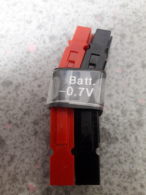
Consider that in the trusdx you can easily power to12.5volts and some people feed with a high probability of smoke at 16 volts.
1 Like
The 12V limit is a recommendation, not a death strip. The BS170s have a maximum source-drain voltage of approximately 60V, which varies depending on the manufacturer and margin. This can be exceeded at high SWR, whether at 12V or 12.6V. Also caused by bad contacts at the antenna or power supply (see above).
Thermal death of the BS170 is rather unlikely. due to the fast SWR protection.
The 9V version differs from the 12V version only in the output transformer’s transformation ratio. With the 9V version, the risk of overvoltage in the BS170 is reduced, and smaller and lighter 2C batteries can be used.
The most important thing at the end.
The few who have problems with the QMX post about it on all channels. The many who are enthusiastic remain silent. Not?
73 Chris
5 Likes
I agree with you. I will opt for the 12 volts version with step down converter, since I have 3s packs.
3 Likes
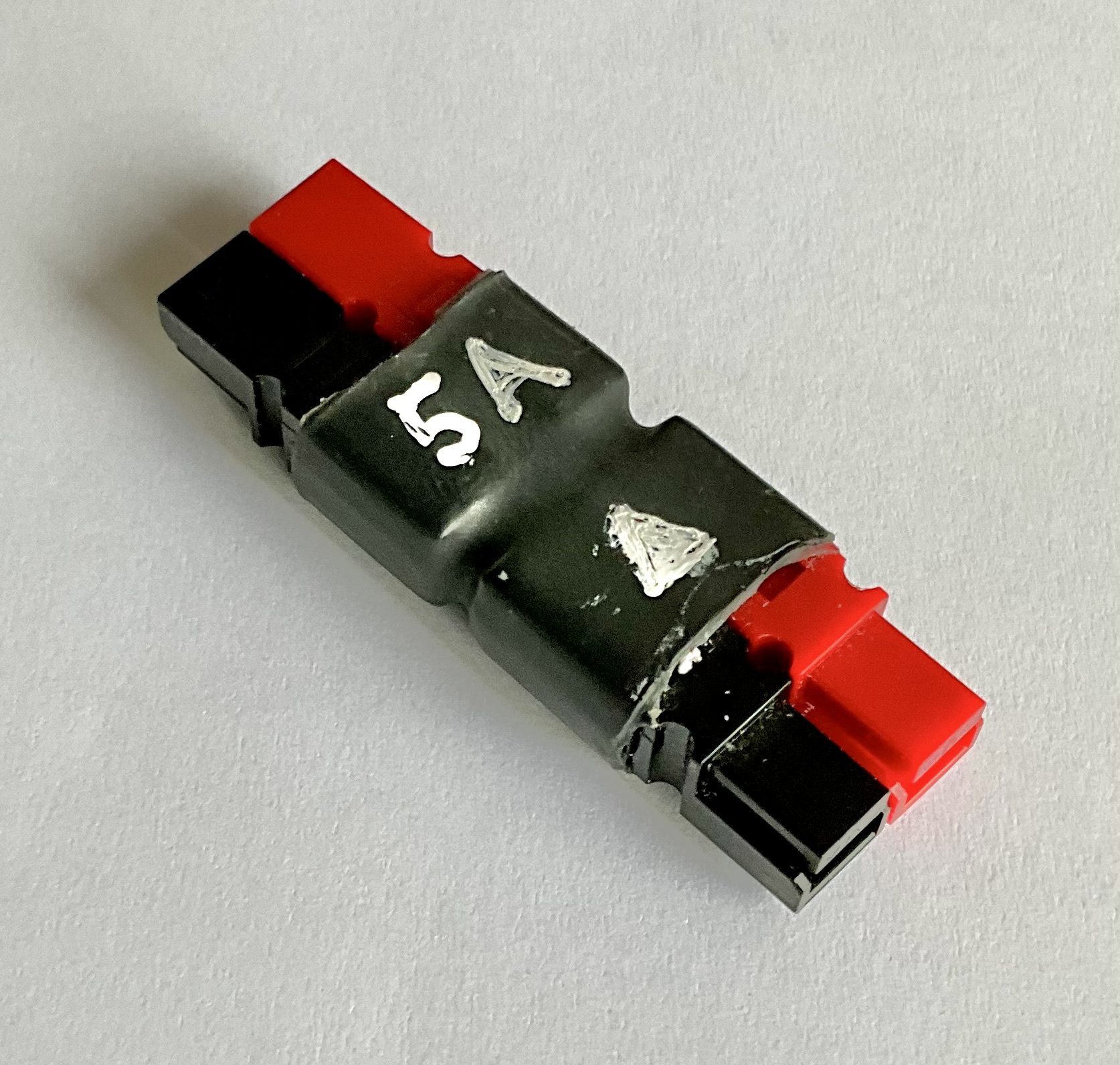
aka 1N5401
3 Likes
I have build a number of different kits from different makers, but this is a first one where you need to stick precisely to recommended placement of elements especially around LPF filters. Hans made excellent build instructions so follow them very closely. Its very important so all elements will fit.
I used tip which gave me 370C temp to make sure that all soldering is done well. Take time do not rush.
When switching for the first time use 7V and resist urge to check power output. Connect terminal utility and do all testing processes. Use dummy load for it.
To preserve your finals initially set SWR limit to 2:1
Good luck.
73, Marek
4 Likes
Here is an example that was used for some time from 2012 onwards with 4-cell LiPo batteries on the KX3 … never used with 3-cell batteries again, neither on the LNR Mountain Toppers nor on the QMX.
4 Likes
I couple years ago I built a QDX. I have decades of experience with DIY projects and soldering, but this was my first radio build.
The two hardest parts were:
-
Reading the part numbers on the small blue capacitors – the print was tiny and the ink color was low contrast with the background. Without a jeweler’s loupe I couldn’t have done it.
-
Winding the toroids. As I said, this was my first radio build, so maybe this is par for the course, but it was tedious work. Plus the QDX had a couple trickier winds, like the trifilar transformer, that caused extra hair-pulling.
The QDX has generally performed well, although I did blow the finals once with a bad SWR situation.
2 Likes
Hi Marek, doesn’t 370 degrees seem a bit too much to you? I work on 230 degrees. 73
You need to use thin tip to solder some elements and they are close to other SMD caps, resistors and semiconductors, most of them are very tiny. Because this is a 6 layer board I use higher temperature.
1 Like
That sounds about right. I use 350C and switch to 400C if the groundplane is sucking away all the heat.
If you use poisonous solder then you use lower temperature.
1 Like
I use a Weller TCP Tip temperature #7 for Lead solder, 370C. I’ve a #8, 420C for Lead-free.
3 Likes
Slightly OT but are those Paul Weller irons any good for the money vs something like a Hakko?
Keen to up my soldering game as all ive used for years is landfill found on Amazon. If I had a decent iron I might be tempted to build more instead of making a pigs ear of it every time I go to try solder something.
1 Like
In fact, I use 60/40, always successful welds
1 Like
I used to use Ersa and Weller soldering irons, then when I saw that the replacement tips were too expensive, I decided to buy non-branded soldering iron and they work well. The success of the solder depends on the quality of the tin. Needless to say, the 60/40 alloy is the best, but it is also the most harmful, so be careful.
2 Likes
I can never seem to find that lead solder for a decent price. For the Planck length worth of solder I’ve used in about the last decade, those whopper rolls you lot use that get delivered weekly to your homes on flatbed trucks with cable winders on them are overkill for me.
I still use the no-name lead free stuff that comes in the little tubes with ‘Unnamed Shenzen Co. Ltd’ irons on Amazon.
I’m ashamed of myself for letting everyone down. Sorry.
1 Like
And yet you complain your soldering is substandard. Use cruddy solder get cruddy results. Also it will destroy the soldering iron bit quickly.
The last Multicore solder I bought now sells for £66 inc VAT for a 500g reel of 0.7mm 60/40. I’ve been using Multicore solders for the last 52 years for a good reason. It gives excellent results.
I bought a 2.5kg reel of 1.2mm 60/40 15 years back and this 500g reel 2 years back. They will probably outlast me. I’ve advised my XYL that the solder is almost worth its weight in Gold.
3 Likes