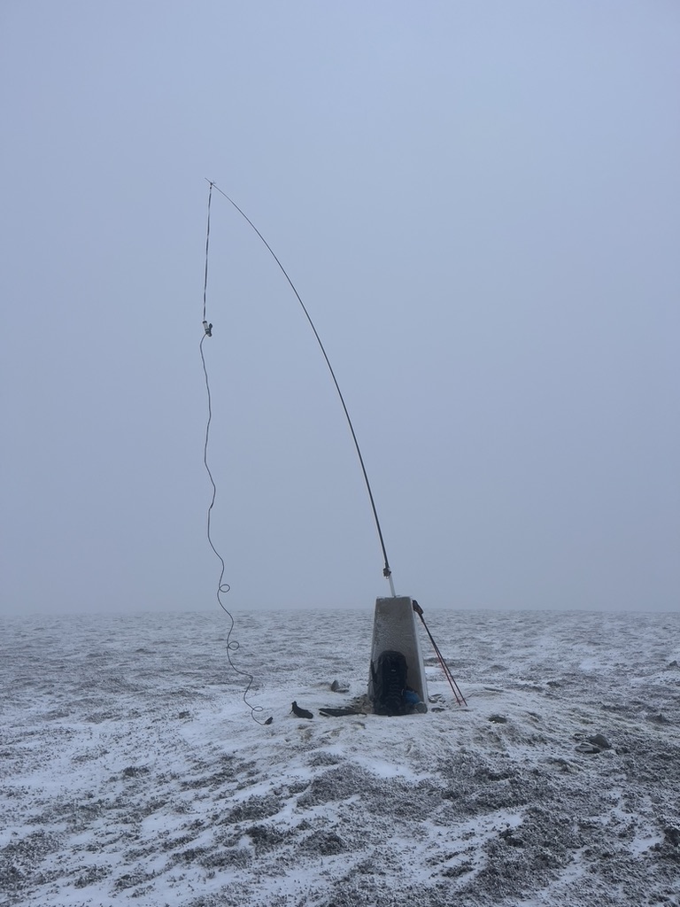
Never had a significant problem, providing the angle of dangle is really high, Like @GM5ALX deployment above or here a recent summit
3 Likes
Interesting as I tested it on a fibreglass pole this afternoon and it still exhibited a high SWR. I didn’t test it when I first bought it so I don’t know if the SWR has changed over the years, although I can’t see why it would. I think I shall build a 2m antenna, as an SWR of nearly 2 with 5w means too much power is going into the ether.
1 Like
I always worry about the use of magic aerials with posh sounding names.
Try to apply the KISS approach.
The humble dipole is the foundation of all resonant aerials.
What we also need is a way to match it to the feed and isolate it from the feeder.
If you do not understand what the aerial is doing DONT use it 'till you do.
Aerial feeder losses occur from high SWR (say above 1,3:1).
Aerial losses occur by absorption in resistive material (carbon fiber),
Get the radiating element as high as practically possible, use low loss feeder.
Stacking 2 aerials delivers 3dB real gain by squashing the radiation pattern.
Renew the feeder at least every 12months…
David
G0EVV
1 Like
Hmm, interesting point of view. It depends to what level of abstraction you think that understanding should be. I bet most of us have a superficial knowledge of theory of operation for most antenna types. For instance, I reckon most amateurs who use Yagis can’t explain how they work.
BTW: I dunno how my 6m flowerpot works [but it does work well on those rare occasions 6m works. Someone please explain why 6m mainly doesn’t work].
1 Like
The flowerpot antenna is a centre fed half wave dipole, with the feedline hidden inside the lower quarter wave. The lower quarter wave is isolated from the rest of the feedline by the choke. At vhf, current flowing on the outside of coax is not related to the current flowing in the inside of the shield. Skin effect is what explains that.
6m doesn’t give you ionospheric propagation when there is insufficient ionisation. The rest of the time it is no better than 2m at long distance propagation. It’s worse than 2m due to lower antenna gain. With 2m, antenna gain can make up for some of the propagation loss, and tropospheric temperature changes can provide bending or refraction of signals to give dx a boost, but dx here is in the 0-2000 km range, unlike the world wide dx provided by the ionosphere on HF.
10m won’t work in a few years time, in fact some ops report 10m is already going off the boil with the peak sunspot activity having passed.
Use the appropriate frequency to communicate, or be disappointed and frustrated.
This is why we have 80m capability for SOTA, to make it possible to make contacts when not even 40m works in the sunspot cycle’s lowest point. 10m at that point is as good as 2m.
73 Andrew VK1DA/VK2DA
5 Likes
…Hi Andrew, great reply, very clear and informative. A great read.
Geoff vk3sq
Could I add a comment about the Flowerpot “choke”.
The impedance at the end of a dipole is in the order of 4000Ohms. To avoid feed line radiation affecting the aerial performance the choke needs a very high impedance.
It needs to be self resonant, where the inter-turn capacitance resonates at the operating frequency with the inductance of the coil.
The diameter, length and number of turns all affect this frequency.
To determine your coil, make up a test coil using the same type of cable but without any tails. Then use a search coil with an analyser to find it’s parallel resonant frequency. Now build the aerial using a coil of the same dimensions.
G0EVV
3 Likes
How a coaxial feedline works, including minimisation of current flowing on the OUTSIDE of the braid, can quickly become a complex matter. Indeed, this reflector has plenty of illustrative content.
Whatever preventative measures are taken to limit current on the OUTSIDE of coaxial cable braid, the effectiveness of these can readily be verified with a simple measurement tool, which is inexpensive to make - see below.
73 Dave
1 Like
Maybe you mean at the outside surface of the braid, in which case ignore the following …
Just for clarification / discussion / or disagreement:
I’m pretty certain current does not flow outside of the conductor. To my knowledge the charge carriers (in this case, electrons) remain inside the metal conductor. An electric current can flow in a gas (like the air), e.g. ionized air molecules as in a smoke detector, and ‘free’ electrons in a vacuum such as an old-fashioned tv CRT.
We should talk about RF energy (not current) outside of the conductor / antenna and which is conveyed by electromagnetic fields (at RF). We want to minimize RF being generated by common-mode current flowing in the inner and outer conductors of a coax feeder. Ideally, the magnitude and phase of the current flowing in the inner is a mirror of that in the outer so the net current is zero and no RF produced by the feeder.
BTW: Electrical energy is not carried by the electrons inside the wires [the drift velocity is very low].
This is true even for DC circuits (though many believe otherwise because they were mistaught this at school). e.g. Energy from a DC battery to bulb goes outside the wires via electric fields and magnetic fields, not directly by the electrons which move as slow as a snail.
Of course, electrons are responsible for losing energy when they collide with each other and metal ions.
1 Like
The more I read of this thread the less certain I became on what I did and didn’t know. Or maybe I became very certain that I don’t know a lot.
I can, however, say that I’ve made plenty of contacts with this model of antenna and this model of mast. My evidence also shows it to work much better the further south I am in Scotland. ES summits only get a hand full of QSOs unless they are more southern ones in Angus, and SS summits are even better.
Probably differences in acceleration due to gravity as there are more people further south and therefore more mass pulling my radio waves into people’s radios.
6 Likes
There’s an inside surface to the coax shield and and outside surface to the shield. Because RF travels only at the surface of a conductor (c.f. Skin Depth) you end up with 3 conductors in coax, centre conductor, inside of shield and outside of shield. Different currents can flow on the inside and outside.
A dipole is a balanced antenna and coax uis an unbalanced conductor. This means, depending on the exact physical properties of the antenna and coax and environment, you can get some of your RF not radiating away from the antenna but picked up on the outside of the coax. It depends on the setup to what extent this happens and how much effect it has. But if you do get RF on the outside of the coax it runs down to your Xiegu and bu**ers everything up.
You can stop it happening by using balanced antennas with balanced cable feeds, or use an balun to connect the balanced antenna to the unbalanced feed. Or you can use an unbal to connect the unbalanced feed to the balanced antenna ![]() Or you can put a choke at the radio end of the feed to “choke off” any current on the surface of the shield. The inner surface current is shielded by the shield (well that’s how that came up with the name) and the choke has no effect on it.
Or you can put a choke at the radio end of the feed to “choke off” any current on the surface of the shield. The inner surface current is shielded by the shield (well that’s how that came up with the name) and the choke has no effect on it.
So it’s simple as ABC, two wires, three conductors, as any fule kno ![]()
Shall we talk about Fowler-Nordheim tunnelling in poly-silicon floating gate transistors next?
2 Likes
I thought you’d never ask…![]()
2 Likes
Hi David,
You are right, the term “choke” is incorrect. I should have used the term “parallel resonant inductor with using inter-turn capacitance to resonate it at the operating frequency” to provide a high enough impedance to effectively terminate the outer conductor at the inductor.
Ie. The purpose of the inductor is to form a parallel resonant circuit which presents a high impedance at its resonant frequency, exactly as a trap does in other antennas.
For this reason the inductor for a 2m antenna is much smaller than the same component in a 6m antenna or a 10m antenna.
Even if it the inductor and invisible inter turn capacitance is not exactly resonant on 144 MHz, it is still providing a reactance that is sufficiently high to effectively terminate the lower quarter wave of the dipole.
The three flowerpot antennas I have built all work as predicted on 144, 50 and 28 MHz.
They give performance that is outstanding compared with a simple quarter wave on the 2m HT, and much better than a doublet on 28 MHz.
As 21 MHz is predictable to become very useful in the coming years, I plan to build a flowerpot style vertical for that band too.
73 Andrew VK1DA/VK2DA
1 Like
Well people may be denser in the south, but overall G is reducing from the poles to the equator. This explains why YBS/SB-021 may be a much less strenuous and sweaty affair than JW/NA-063
4 Likes