That’s fine for SOTA as long as you use a rotary converter to make the HT.
3 Likes
Pure nostalgia! My first “proper” AM transmitter was built to the G5RV Elizabethan design in 1960. It had a pair of 807s in Class C in the PA, plate-and-screen modulated by another pair of 807s in Class B Zero bias. And yes, the modulation transformer was a Woden UM2. What else?
The HT voltage on the 807s was 750v.
73,
Walt (G3NYY)
1 Like
How very restrained of you Walt ![]()
Well, I wanted the 807s to last a long time. After all, they cost me 3/6d each!
73,
Walt (G3NYY)
1 Like
Class C using AM, I would imagine that not working too well.
Surprised the DX100 has not been mentioned yet. I recently rescued one from being skipped at a certain establishment that I attend.
Plate modulation young man, plate modulation ![]()
Yes, but doesn’t the mod push the PA stage into compression at full modulation ? Unless with the PA valve running constantly with the carrier power being greater, thus it stays linear… hmm thinking
One of the problems with the ART-13 is the under sized mod transformer. It could have been made bigger. Mine gets so hot at times you can hear the windings of the mod transformer acoustically vibrating to my voice. I have a small temporary PC fan to keep the compartment cool. Its like a boiler room in the back of that after a good old rag chewing session.
Yes, the anode current meter should not twitch with modulation. A little boring / unnerving once you are used to SSB ![]()
You will find copious information on AM and class C PA if you look. Most of it will be at least 40years old.
This may help: http://www.arrl.org/files/file/Technology/tis/info/pdf/5602039.pdf
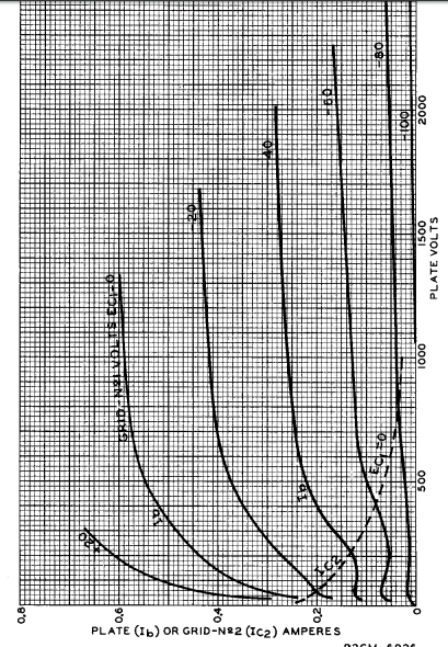
Scary to think my dad would have been 1 year old when that was written - 1956. Some deflection is evident, no mod the 813 runs at 120mA. Fully modulated it will swing up to 200mA. Nearly a half shift in plate current.
Per the book that seems normal, as its indicated by a red band on the meter.
Jonathan
That’s only if you turn the mic gain up to 11 ![]()
Gah, this thread has drifted, and I have spent much time down memory lane! Just flicked through my RSGB Communications Handbook 4th edition, 1968.
The two example AM / CW transmitters using valves both use low level mod and a linear PA stage…
Anyway, the new HF Band plan…
That seems to fit the Marshall amplification philosophy and marketing strategy. Amusingly it doesn’t have any mic gain setting ![]()
(Sorry) back to bands and rules.
Well, my go to resource is the RSGB and if it differs from the IARU bandplan in a way that effects me it will be the RSGB version that I follow, if only because I have it accessible on the computer!
Brian
Or click the link in the first post.
You must be splattering all over the band!!! (Unless, of course, you are using some form of “controlled carrier” modulation, for example series gate modulation. Such methods were described as “efficiency modulation” in the old days. The Labgear LG-50 used this system.)
73,
Walt (G3NYY)
P.S. In 1956 I had already been a short wave listener for a couple of years.
![]()
It does actually use the PA in class C interestingly.
You can not simply deduce that it is “splattering” with the values I have stated Walt, they are perfectly within the range of the 813 operation region. I also stated nothing about grid drive voltage before. It is in fact perfectly clean on air, and is often commented for such good performance.
The 120mA current is actually the combined current for the modulator and PA stage, which I have later realized through reading the ART13 manual. The grid voltage is around 60V but that represents a combined indicator with the applied VFO drive. Anode voltage on the 813 is approximately 1900V
Sometimes the front reading meters on these old sets are somewhat open to different interpretations from first glance.
Thank you for sharing the above book snip though Walt, that was a good read !
Jonathan
That is a completely different situation than the one you first described! Yes, if you are measuring the sum of the PA plate current and the modulator valves plate current, there would be a considerable variation during modulation. The PA anode current should be constant, but the modulator plate current would vary from a very low value to a maximum current on speech peaks. (Perhaps 0 ma to 80 ma.)
I’m not sure how you can be measuring the combined current, though, because the plate voltage on the 811A’s must be a lot less than 1900v. Are you not using separate HT supplies for the PA and the modulator? Or are you feeding the 811A plates through a dropper resistor?
Ha! Just looked at the manual. Unusually, they use two HT supplies in series!
“The ART-13 requires two distinct high voltages, that is 1,150 VDC @ 300 mA for the power tubes plates and 400 VDC@ 225mA to power everything else. Accordingly the dynamotor has two windings, a 400 VDC winding and a 750 VDC winding that is put in series with the 400 VDC one, so producing 1,150 VDC. When the multi-function meter switch is in the P.A. PLATE position, the meter measures the current flowing through the 750 VDC winding, so effectively measuring the total power tubes (RF + audio) plate current in any condition.”
That explains it, but it’s a very unusual arrangement.
73,
Walt (G3NYY)
Its a very easy misinterpretation to make, as most transmitters just measure the final PA current using the front panel meter. Until I opened the manual to recheck, I just quoted the actual meter reading itself without realizing that it was measuring the supply current through the modulator as well.
Like most equipment of that era, the norm varies considerably, which is why its interesting - well, to me anyway !
Yes my homemade PSU, stacks the supplies as per the dyno. As far as the transmitter is concerned it controls and operates in the same way.