No large trench needed. The wire can simply lay on the ground. My suggestion to bury it was purely for the WAF (Wife acceptance factor). Even 1/2" under the surface should be enough that it’s no longer visible. The shape is not critical, in fact you can even put multiple loops down and connect them together and it doesn’t have to be under the antenna - it’s all explained in the article.
73 Ed.
1 Like
If you are interested in experimenting, The Sept 2019 QST, pages 30-32, has an article “A slightly off-center-fed-dipole” by Brian Machesney K1LI/J75Y. The dipole is split 45:55 and claims operation on 8 bands.
I am suggesting this, as the idea was to use a balanced antenna to help reject noise and this design is less unbalanced than the usual designs.
Ian
VE6IXD
You mean just lying there on my lawn and garden where my wife [a keen gardener] will see it ten times a day and she and the dogs will trip over it?
That’s why I said bury it!
The point is you don’t need a deep trench, just enough so that it’s out of site. Now the problem you might have of course is that the dog or the wife, while digging holes my dig into it, but putting it as far out as possible, should reduce that chance.
I take it you don’t have any radials buried at the moment - as that would be a far, far bigger problem!
73 Ed.
1 Like
Think we’re going round in circles now, Ed. I can’t bury or lay a counterpoise on the ground. I’ve ruled out an antenna requiring a good ground plane for that reason
OK, to be clear the system can be buried or simply laid on the ground it works the same. In your situation I would bury it just under the surface to keep it out of the dog and wife’s sight.
I think you’ve decided on trying an OCF in any case, so it’ll be interesting to see how quiet that is compared to the long wire.
73 Ed.
1 Like
Ian, I wish I had access to an antenna analyzer which would probably help me optimize the wire lengths. The analysis I summarized in the chart above gives me 8 bands including the 5 bands I use mainly from the home QTH. So, I’m going to try the 20%-80% ratio first.
Just to put this whole thing into prospective, the vast majority of my operating is up on the hills as a SOTA activator. At home, it’s mainly chasing on HF and VHF. I don’t do contests or special events from home so I don’t need [and could not erect] a high performance DX antenna system. My existing antenna is adequate except for the high low-band noise. If the planned OCFD improves the low-band performance that will be just fine and - with my stealthy implementation - won’t cause friction with family or neighbours.
Thanks everyone for your suggestions and advice. I’ll report back on this thread once the new antenna is up and I’ve had enough time to evaluate it.
73 Andy
2 Likes
Two months ago, I said I would report back when I had the new antenna working. Well, my first two attempts at making and positioning a homemade Off-Centre Fed Dipole for 80m-10m were not very satisfactory and, feeling downcast after my efforts, was even thinking of reinstalling the old end-fed long wire despite the high background noise that prompted me to create this thread in the first place.
Also, moving the house-end antenna support point from the bungalow chimney to a mature tree at the edge of the property [to be near the outside shack] meant the wires getting entangled in leafy branches and the antenna wires being less out in the open.
This morning I decided to try yet another short leg to long leg length ratio (19.5% to 80.5%) and move the 4:1 current balun from the tree branch to the chimney. I choose a total length to suit the CW section of 80m (and higher bands). The long leg (33.25m) fits perfectly in the distance to a high tree at the bottom of the garden and the short leg (now reduced to 8.06m) needs to run only to the corner of the roof rather than a messy highly-visible run over my wife’s car to the neighbour’s overhanging tree branch.
Armed with my brand-new Rig Expert AA-35 antenna analyser [funded through the recent sale of some radio gear] I quickly did an all-bands SWR scan followed by ones for individual bands.
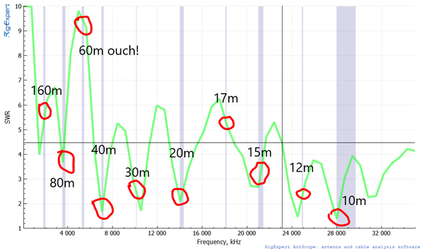
The author of the on-line article in which I read about the 19.5%-80.5% split warned that the SWR for 17m was poor so that came as no surprise. The bad SWR for 60m was a big disappointment – as it’s one of my favourite bands – but as it’s not harmonically related to the main A.R. bands, you often read about this problem with multi-band antennas.
My LDG Z11 Pro 2 ATU does a good job of matching the OCFD on the ‘bad SWR’ bands (80m and 15m) [only the CW sub-bands tried so far] indicating an SWR from 1:1.0 to 1:1.5. It even does the same for the 60m UK CW sub-band (around 2560kHz). But it complains about 17m by rattling its relays forever.
The background noise on all bands is much better (quieter). For example, even with lightning QRN today, noise was S7-S8 on 40m where as it was consistently S9 +5 to +10 with my old end-fed long wire. Even the 3s cyclic ‘ticking’ noise on 6m is much reduced and I can clearly hear the GB3NGI 6m beacon in N.I.
I had time this afternoon and evening only for a few CW QSOs - on 80, 60, 40 and 30m getting excellent reports [except on 60m] running 15W or 25W.
Well, more tests to be done in the coming weeks but I don’t expect any big surprises. I think I’m all set to do a bit of chasing from home now.
6 Likes
Well done on all the work Andy.
As you rightly say multi-band antennas have to be a compromise.
I don’t know if you have the room (most of us in Europe/UK don’t I think) but as you say the main issue with this antenna is 60 metres not being resonant (and whether or not the ATU manages to match it, it still won’t radiate well) - have you considered putting up a single band dipole for 60m in addition to the OCF? I know even if you have the space, the WAF (Wife acceptance factor) factor may be an issue but that may be the best technical solution. Who knows in some way the ATU might even match a 60m dipole better than this OCF on 17m?
In any case, WELL DONE on what you have achieved so far.
73 Ed.
1 Like
Thanks Ed. I’m very lucky to enjoy a high WAF but another overhead wire in the garden would be pushing my luck.
Hi Andy
have you considered a loop-on-ground receiving antenna for the low bands ? See for example http://www.kk5jy.net/LoG/
I have tried one briefly and was surprised how effectively it cancels local noise. From my tests with the wire laid on the grass, signals are typically 10dB down but noise is 20dB down. I haven’t yet worked out how to do Tx/Rx switching - I am considering buying a separator adapter for my IC-7300.
If you have a sensitive receiver you don’t need a preamp.
Cheers
Rick
Rick, thanks for the suggestion. Is this to solve the high-SWR-on-60m problem I have with the new OCFD or as an alternative to the OCFD?
Re 60m, the problem’s on transmit not on receive. In any case, laying antenna wire on the ground (or burying counterpoises under it - as previously suggested), is totally impractical in my garden [as discussed at length from post no. 66 above].
As I said a few posts back, the low-band noise is much reduced with the new OCFD compared to my old end-end long wire.
Regards, Andy
Hi Andy
I meant it as an alternative to any “in the air” antenna that is picking up excessive noise on receive. The ground quality isn’t relevant as I understand it - it works as well around a concrete yard.
Rick
Andy,
Congrats on the achievement. Your signal was very good when you chased me yesterday.
73,
Guru
Thanks Guru, our QSO was the first of several I’ve had on 20m using the new OCFD and it seems to work quite well. Think I was using either 15W or 25W. The reduction in background noise across all bands has helped a lot listening to weak signals.
2 Likes
I am not sure whether you found a solution, but what usually helps is
-
QRM Eliminator
Amazon Link -
Ground Loop Antenna (as suggested here by other members).
I also live in town and the QRM Eliminator can eliminate most of the times (not always) human-made noise so that a weak SOTA station can be copied.
Kind Regards,
Chris, DL1GKC
EPILOGUE:
Although very pleased with the big reduction in background noise using my new homemade 19.5%-80.5% OCFD compared to my old EF LW, I was irked that even my LDG Z11 Pro II ATU couldn’t cope with the 1:10 SWR on 60m (I know it’s asking a lot).
I read that, not only the wire thickness (I’m using thin UltraLite wire), but the type of insulators, feeder (e.g. coax, ladder line), nearby buildings (the 4:1 balun is on the side of the chimney), trees, ground conditions, etc have a noticeable effect upon the electrical length making an accurate length calculation difficult if not impossible in practice.
After reviewing my antenna analyzer SWR plots for each band, I revisited the basic calculation for the total length of a ½-wave dipole and determined I had made it a bit too long.
I shortened the long and short legs by about 60cm and 15 cm respectively and measured the SWRs again. The SWR ‘dips’ had shifted a bit and the ATU could now load up across the 60m band (Harrah!). The 60m beacons and many stations are very strong (5/9+) and I’ve had 58(9) and 59(9) reports on CW and SSB QSOs using 15W.
The SWRs on 80m are not quite as good as with the previous un-shortened wire lengths but that’s making no practical difference. Performance on the higher bands, 30-10m (with the exception of 17m as previously discussed) continues to be excellent.
I’ll not try to tweak it any more as I’m bound to make something worse. As many have said, multi-band HF antennas are a compromise and this one is about right.
Thanks everyone for your suggestions and comments.
73 Andy
2 Likes
Could you summarise the final dimensions and feed system, please Andy. Any solution giving practical multiband operation will be useful to others.
Thanks 73 Andrew VK1DA/VK2UH
1 Like
I settled on a 19.5% to 80.5% split for the short and long wire legs. I optimised for the low end of 80m because I’m mainly CW mode. I chose a bit low (3520kHz) knowing that it was easier to cut wire off if the resonant frequency was too low than add extra wire on.
As discussed in my last post, there are many factors in practise than can’t be quantified for the length determination, meaning that the length may need adjusting after SWR and X,R measurements are made once in situ (which is why I recently bought a Rig Expert AA-35 antenna analyzer).
The ½-wave dipole total length calculation gave 40.53m with the leg lengths 32.62m and 7.91m. I found it difficult to measure out the wire to better than about a few mm. In any case, the sag due to the weight of the wire (~100g for the long leg) must shorten the effective length.
Low visual impact was an important consideration.
Components:
• SOTAbeams antenna wire - PVC-covered, stranded copper wire, 0.22mm² total conductor CSA (approx. 24awg), velocity factor 0.97, weight approx 3.3g/m (colour brown – virtually invisible from the ground - mid grey would be even better against the sky)
• 4:1 current balun - Guanella, 2x FT240-43 ferrite cores, 400-W rating, waterproofed, 485g (small white box on white-painted wetdash finish of chimney stack)
• Coax feeder - 20m of 50Ω RG8X with PL259s (cable upper part spray-painted in disruptive pattern).
Antenna supports:
• Balun attached to bungalow chimney stack (approx. 7m high++)
• Short-leg wire (sloping) to nylon cord (approx. 1.5m long) to gutter bracket at corner of roof (end of antenna wire approx. 4.5m high)
• Long-leg wire to bungee cord (approx. 2m long) tied to multi-stranded nylon cord Halyard (dark green to blend with tree foliage). Halyard goes over branch of mature tree (approx. 15m high++). The halyard is used to raise or lower the bungee support cord for the far end of the long leg as one would for a flag or a sail. The bungee 1) gets the end of the long wire out of the branches and leaves and 2) prevents the wire being stressed as the tree sways about in strong winds.
++The long leg is roughly horizontal but the garden slopes downhill from the house to the large trees at the bottom of the plot, so the antenna wire gains height above the ground as it runs to the tree support.
The 20m of coax feeder runs vertically down from the balun to and briefly along the rain gutter then across to the shack (an outside building about 2m from the house) under its rain gutter and in near the door and then to the operating desk. The firm that makes the current balun says additional choking (loops of coax, ferrite rings etc) shouldn’t be necessary.
3 Likes
Thanks Andy for your dimensions etc. Very useful, might have a go at building one.
73 Geoff vk3sq
1 Like