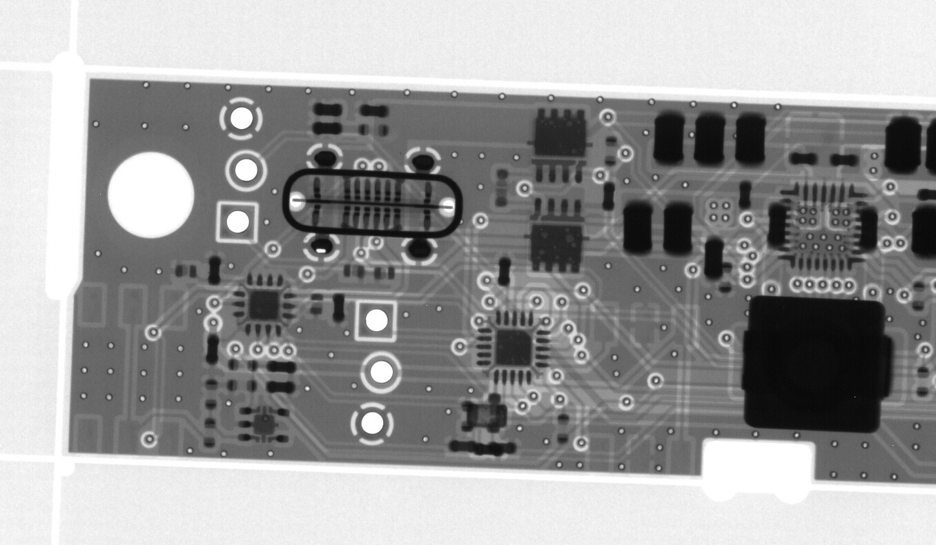
Quick status update: rev2 boards are on the way to me from China (X-ray looks good ![]() ). Two spare rev1 boards have arrived for testing in DL and GM land. The firmware is almost complete, with lots of improvements made in the past few days (cut standby current down to 60 µA, implemented watchdog, LED animations, thermistor handling, 4S LiFePO support etc.).
). Two spare rev1 boards have arrived for testing in DL and GM land. The firmware is almost complete, with lots of improvements made in the past few days (cut standby current down to 60 µA, implemented watchdog, LED animations, thermistor handling, 4S LiFePO support etc.).
11 Likes
Great stuff! I recently bought a bunch of LifePo’s from that Grandad Web site @MM0EFI kindly pointed to recently.
I got 3S, 6S and 8S battery packs for my KX2 and Venus SW-3B. Would the fw support 6S And 8S or is that pushing it a bit too far?
The BQ25792 supports up to 18.8 V for the VREG setting, and its absolute maximum rating on the BAT pin is 20 V. So a 6S LiFePO₄ would be pushing it too far. But what is the point anyway, given that the KX2 is rated for max. 15 V supply (and PA efficiency is probably significantly lower at higher voltages)?
I recently tested the capacity of my 6 year old Ansmann 3500 mAh 3S Li-Ion battery (several hundred cycles, usually charged at 2 A to 100%), and found it to be 3050 mAh from 12.6 V down to 9 V at 2 A. It still gives me several hours of operation at 10 W under all temperature conditions.
6 Likes
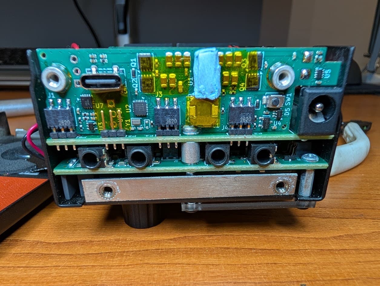
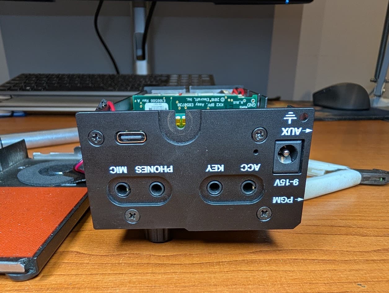
Another status update: rev2 boards have arrived, and everything’s looking good! About the only (cosmetic) hardware issue that remains, as far as I can tell, is the fit of the light pipe for the RGB LED in the hole in the back of the KX2’s case.
Seven rev2 boards are on the way to beta testers on three continents. I had to make a selection, with priority given to those who are ready to program AVRs.
In case you want a sneak peek, assembly instructions for rev2 are here: Hardware rev2 assembly instructions · manuelkasper/kxusbc2 Wiki · GitHub
Attention has also been given to detail – here is the (prescaled /64 = 512 Hz) RTC frequency of one of the new boards, after “factory” calibration has been applied.
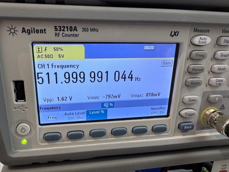
(Frequency counter with external Rubidium standard)
73, Manuel HB9DQM
6 Likes
Nice progress report. Hoping the beta tests go well. Whatever the outcome, please stick my name on the ‘just take my money already’ list please and thank you. ![]()
2 Likes
I would definitely be interested in one for my KX2 as well.
1 Like
I don’t know how I missed this thread - I’d certainly be interested in one for my KX2 ![]() thanks for pointing out the thread @MM0EFI
thanks for pointing out the thread @MM0EFI
73, Ben
GW4BML
3 Likes
Manuel’s attention to detail in the RTC sums this project up! He has done a fantastic job with this project, feels very mature already!
I am a rev1 tester and its working great for me. I completed the SMT work on the board and now have the AVR flashed with latest release of firmware.
Its working great. More testing and documentation of different scenarios to be done, but have not found a charger which does not work as expected so far. OTG working on all the phones and Battery Banks I have. RTC working well also, even in the rev1 board.
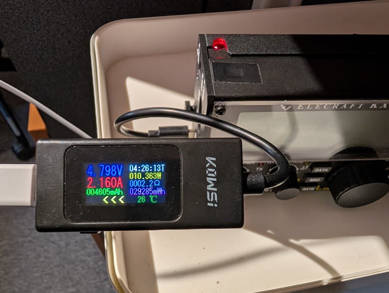
Here are some pictures I have taken tonight.
Charging with a Samsung A55 charger
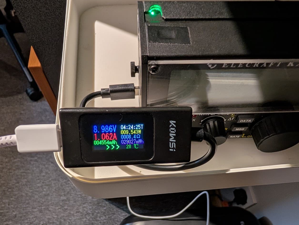
Charging with a Google Pixel 30W charger
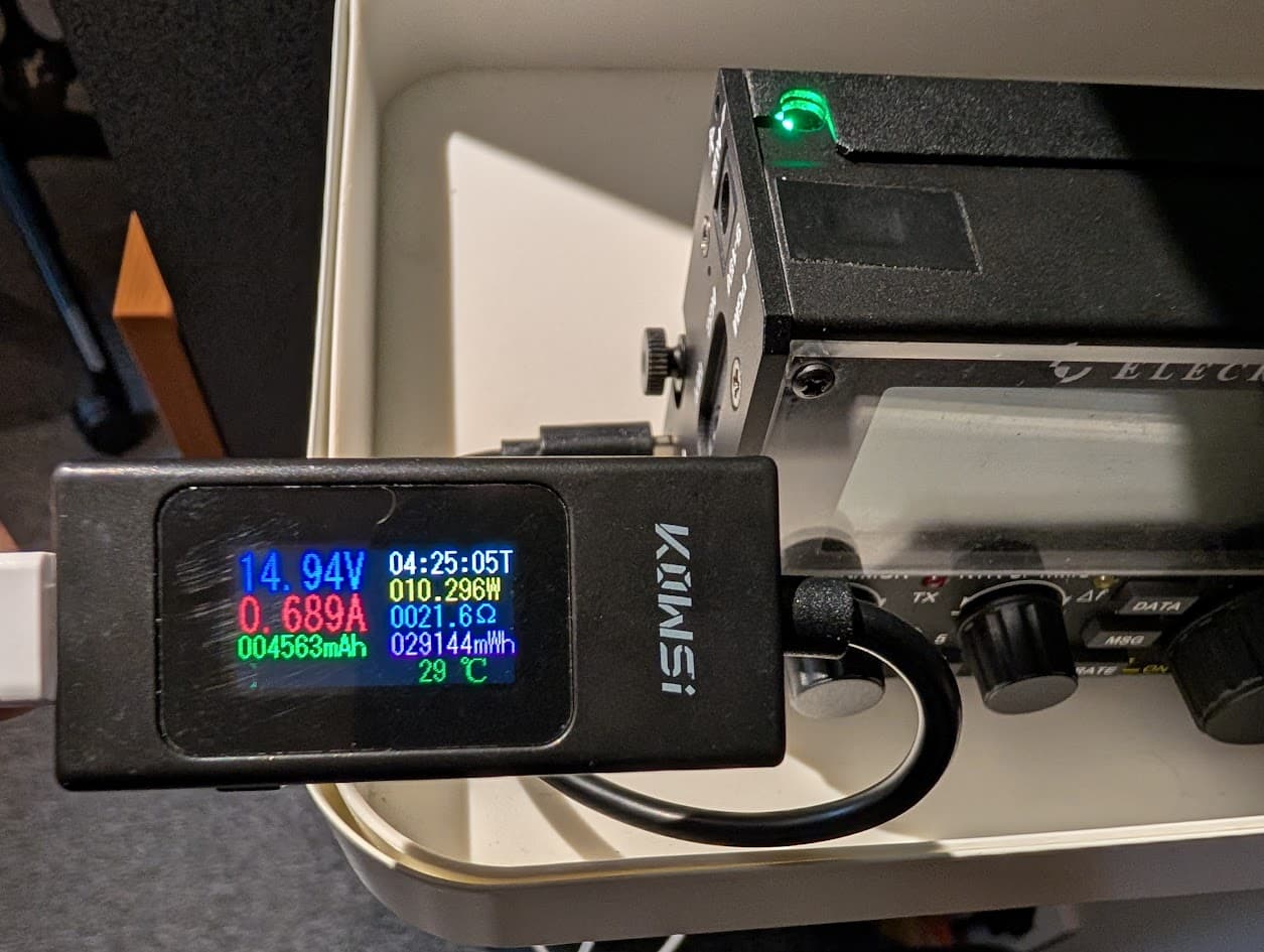
Charging with an old Sony 1.5A USB charger
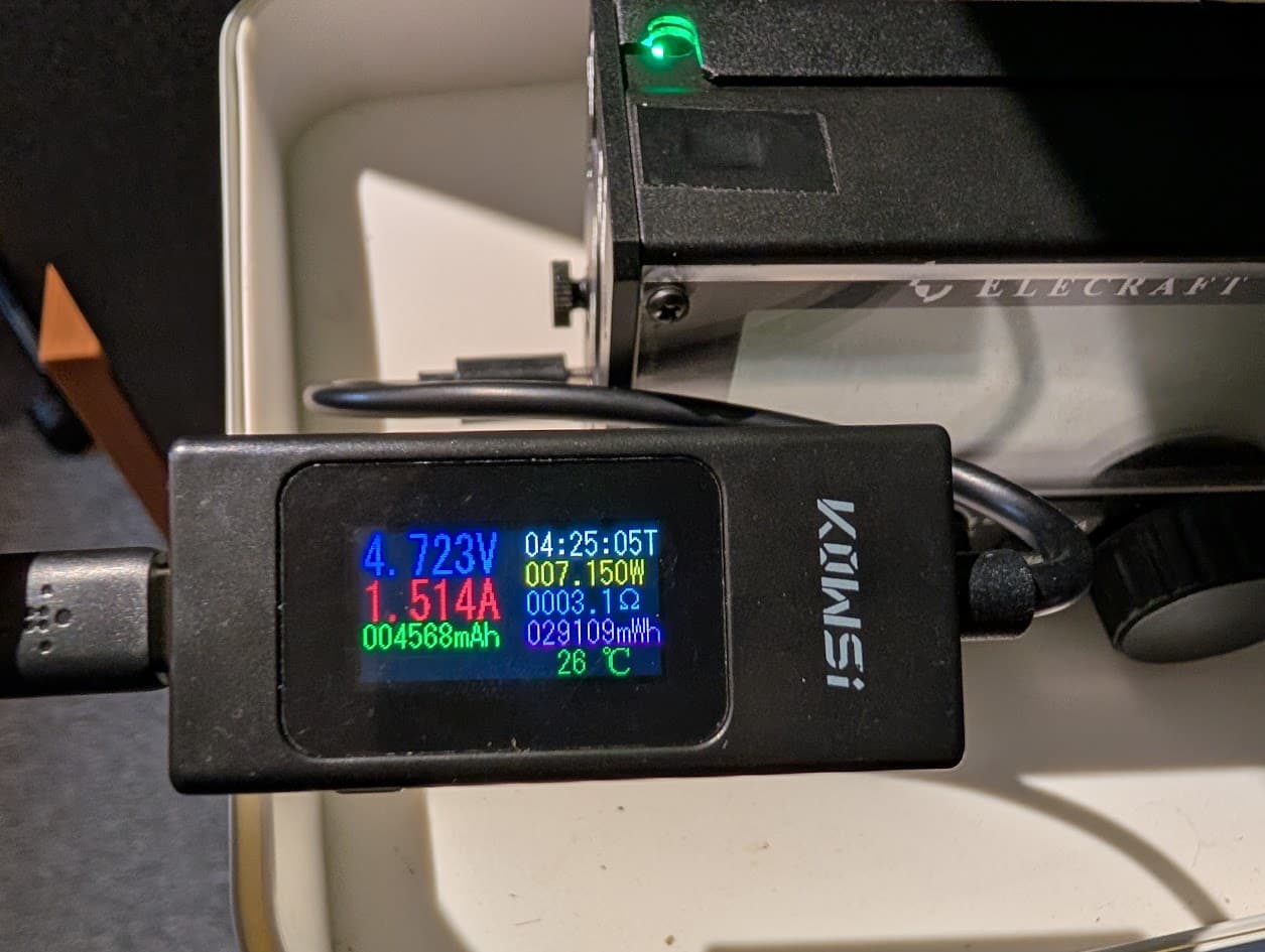
Finally in OTG where the KX2 is charging an old Anker 5V only Power Bank. LED on KX2 is now Red and the direction arrow on USB-C meter switched!
73 & MX Gavin
GM3GAV
11 Likes
This looks like a fantastic project.
Many of us, at least here in the US, like and use the protective KX2 end panels from Side KX. Mine are in rough shape now after some clumsiness on my part on a couple of activations, so I wouldn’t hesitate make my own rough USB-C opening with a drill press and files, but I think a lot of folks would like a premade panel with the protective handle. I wonder if Scott NA0MT (who makes the SideKX panels) would be interested?
2 Likes
Hi @HB9DQM Manual,
Absolutely fantastic, I need one ! Please can you put me down if possible, happy to test.
This would really help in multiday SOTA expeditions, just standardising around one external PD source for all kit, GPS/watch, phone, head torch, kx2, sat messenger, etc.
The existing Elecraft board KXIBC2 is basically useless as I never have a high enough voltage to charge when in the field (Campervan or external batteries). It was also poorly designed, kept shorting my battery to the metallic casing until I modified to correct !
Tim
2 Likes
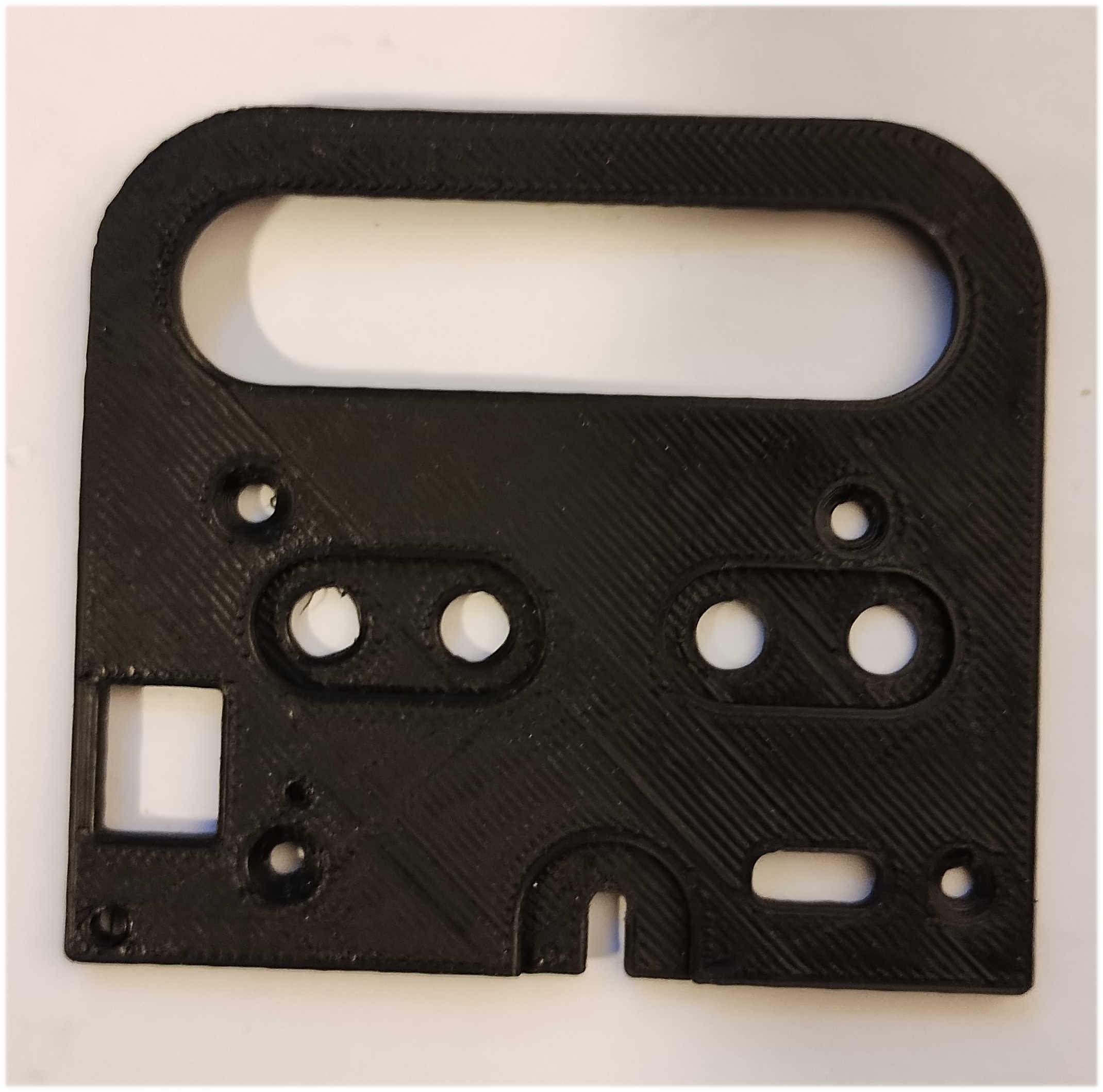
Nice job on the design, but I’d feel weird with one side 3-D printed and the other aluminum. And the other side is the heat sink for the PA so plastic would be no good.
It’s just a prototype to confirm the drawing dimensions are correct.
1 Like
The STEP file from which @GM4LLD’s prototype was printed is now in the repository: side_panel_handles_s.step
Users can have it CNC milled by some service, or perhaps when we’ve got distribution of the KXUSBC2 sorted out, it could be an option to order that instead of a regular side panel. The goal is not to take away any business from Scott, so only the left side panel shall be made available – but I can see the need to have both upgrades at the same time (KXUSBC2 and Side KX). The same goes for the similar Windcamp Shield Kit.
At the moment I don’t have any spare boards, but once the feedback from beta testers comes in and we iron out the last remaining issues, it’s mostly a matter of distribution to get everyone their KXUSBC2 ![]()
That sounds bad – can you elaborate on where it shorted, and what you did to correct it? As the KXUSBC2 uses the same electrical and mechanical connections to the KX2, it might also benefit from those modifications.
73,
Manuel HB9DQM
1 Like
Perhaps it would suffice to include a template (drawing on paper) with the documents… the cutout for the socket can be made quickly with a drill and a small file.
73 Armin
1 Like
Your wish is my command ![]()
(and luckily the 3D CAD software makes it super easy)
2 Likes
Easily done. Me first, then everyone else. ![]()

What particularly catches my eye is the chosen dimensioning of the objects; is there perhaps another option for manufacturing? ![]()
1 Like
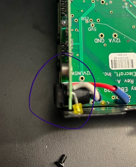
It was difficult problem to find, ruined several activations, batteries and probally my board, until I was able to diagnose.
The soldered wires on the back of the KXIBC2 board are not flush, especially the live terminals used to wire to the board and that was intermittently causing a short against the side panel.
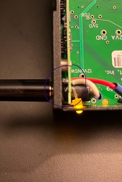
It would blow the fuse of the battery or BMS. And the radio would die when this happened.
Once I diagnosed which took some time, I trimmed the joints and added Kapton tape to the side panel for extra measure.
It’s never worked right, I suspect issues caused on my board by the shorting of the KXIBC2 to the ground. I have been reluctant to try getting a new one as the shipping cost is ridiculous, for a what is basically a warranty issue in Europe. To be honest, buying this board and shipping it over was an impressive waste of money, time and activations ![]()
2 Likes
Hey Tim, was that factory installed or added afterwards? I don’t have mine with me right now, but I seem to recall it looked different.
I absolutely agree that is not an accessory that is worth getting, at least for my uses.
3 Likes