6dB is not 75%
6dB is 4 times in power or 2 times in voltage
so 25% in power and 50% in voltage
6dB is not 75%
6dB is 4 times in power or 2 times in voltage
so 25% in power and 50% in voltage
I may be wrong, but 6 dB less means minus 6dB, which is 1/4=25%of the baseline, and in terms of signal-to-noise ratio under otherwise identical conditions a loss of 75% (relative to 100%).
Or am I missing something?
Sorry, I misunderstand you.
Yes, 4 times less in power is 75% loss
Agreed, 6 dB loss is commonly understood as
10^(-6/10)•100% in power
10^(-6/20)•100% in voltage
Michael,
It is indeed as Martin briefly summarized above.
It’s understandable that one is primarily concerned with something that one can see and hold in one’s hands and not with all that is hidden.
With the mechanically as short as possible antenna you are aiming for limited space (in your case typically for densely overgrown/wooded hills), one would have to worry above all about the influence of the antenna properties by objects that are all around at a distance of less than lambda/2.
A very hidden and therefore often overlooked, not exactly complex, but for various reasons very difficult to record influencing factor also has an effect in the above cases from the following facts:
Free tip
Simply realize a few hundred SOTA activations with a few tens of thousands of QSOs and don’t think that when particularly special events occur, you can/must explain quickly the cause of them, because there are usually too many unknown factors for that.
73 gl, Heinz
Or, scientifically: If you want to understand causal effects, you have to
a) control, in a randomized fashion, a single variable that we assume causes some effect,
b) keep all other variables as equal as possible (“ceteris paribus”);
c) measure and repeat the measurement often and trying to avoid any pattern in the timing of the measurements/experiments (otherwise, if you always go to the pub on Saturday nights, and your friend Joe does the same, you might assume that Joe is spending all of his life in the pub).
While we sometimes have to accept a compromise, the above is a good and practical guideline - e.g., it is better to run two WSPR beacons in parallel than to do sequential antenna tests.
Also, the better you can isolate aspects of your model, the more you will be able to discover.
For instance, measuring the efficiency of a broadband transformer with the setup described by Owen Duffy (and explained very well by Heinz in this forum) is better than using two transformers back-to-back, which in turn is still better than assessing a complete antenna system by the number of QSOs.
In these sad times of alternative “facts”, esoterics, and clickbait journalism, we as radio amateurs could and should evangelize the ideas and keep alive the torch gifted to us by the heroes from the age of enlightenment; of which some paid their insights with their lives…
Simultaneously testing two antennas using synchronised WSPR transmissions, when done carefully, can give excellent results. It’s important to get lots of data though. Hundreds of data points are needed for anything useful to be concluded when the potential differences are small.
Spot On!
With bands going up and down a lot at the moment, lots of data points are needed and the best would be as you say to have two synchronised (and identical output) WSPR transmitters connected to the two antennas under test at the same time testing the antennas on the same bands at the same time.
73 Ed.
Unless you employ Taguchi methods and the variables are independent of each other and the changing tests.
Would that involve borrowing 5000 FT817s and grading them to get two with identical outputs?
Possibly, but don’t confuse it with Tamagotchi methods which will demand your attention every few hours. ![]()
These analyses are all well and good, and interesting in their own right, but at the end of the day a successful activation of a summit comes down to so many factors that it would take an army of geniuses to figure them all out.
For me, the issue is simple - can I get some contacts - any contacts - from a summit, after I’ve set up my limited gear the best way I could, given the circumstances? As far as antennas go, I personally have two choices - a linked dipole or a vertical. Depending on the circumstances, I’d take one or the other: lots of trees on the summit => take the dipole only; very little space on an open summit => take the vertical. If it’s a long walk-in, take the lightest and hope to fate.
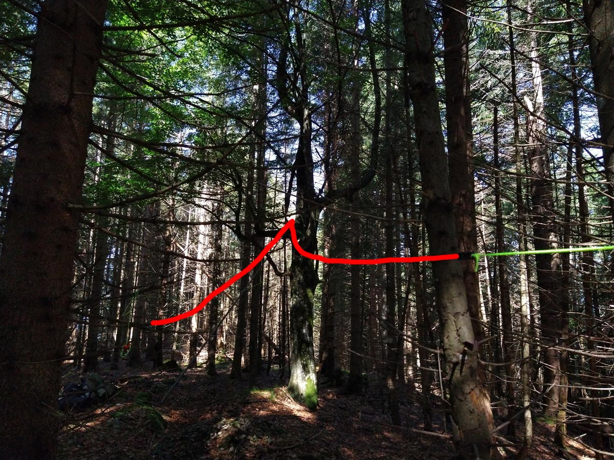
Here’s one snapshot from my activation last year of the Brandkopf DL/BE-028, where I set up the linked dipole for 20/40 meters in far from ideal circumstances, with the 7-meter pole leaning against a tree, and the antenna strung out between the trees where it could fit - I’ve sketched roughly where the wire was strung heading away into the distance (the small pile of stones just beside the left-most tree is the summit cairn ![]() ):
):
With this complete pig’s ear of an antenna I made 25 QSOs, on 20m and 40m, with the furthest 40m contact OH3GZ 1500km to the north, and the furthest south EA7GV on 20m at 1700km, all with excellent signal reports using 15W on SSB. I’ve deployed this antenna in several similar circumstances on SOTA summits and have regularly got a decent number of contacts before they dry up.
If I were to listen to people tell me that this antenna has no chance of getting a signal out, with all those trees around, I’d have stayed in bed until 9 and had an early liquid lunch.
No amount of modelling in EZNEC, nor optimization of antenna type, height, build or materials, etc. is going to be able to beat just putting the antenna up, switching on the radio and … the rest is up to you.
Just my $0.02,
Rob
[quote=“DM1CM, post:73, topic:26749”]
Here’s one snapshot from my activation last year of the Brandkopf [DL/BE-028][/quote]
That could just as easily have been a photo of any of my many activations of DL/AM-180 Berndorfer Buchet - Like yours, my linked dipole on a 6-metre squid-pole there works despite being surrounded by trees, in fact, it has delivered S2S SSB QRP contacts into VK on more than one occasion.
I did once try a vertical there - never again! It was impossible to get any contacts. the vertical trees and vertical antenna simply do not go together well.
This echoes your point of having two dissimilar antenna systems and choosing the best one for the site as required.
73 Ed.
It’s not about the answers. It’s about the questions.
It doesn’t matter where you feed a halfwave wire, it radiates the same. It’s about how. If you deploy the halfwave wire as an inverted-vee, then feed it on the end… it will radiate exactly the same as if it was fed in the center.
By feeding it on the end, you can eliminate the weight and loss and the time to uncoil and coil the coax. You also eliminate the connectors which when often manipulated may have a broken connection so multiple points of failure are gone. without the weight of the coax, you can use a much lighter pole, and lighter wire.
I use #28 teflon wire. My antenna weighs about 40 grams including traps for multi-band operation. My pole weighs 209 grams and extends to about 6 meters while collapsing to about a half meter. Makes for a very easy carry.
The end of the wire plugs directly into an adjustable unun which plugs directly into the radio. The unun is built in a dental floss case and weighs 18 grams. It tunes the antenna to 1.1:1 and has a measured loss of about a half DB.
With such a light weight wire and the pole leaned away from the wind, it has never broken, nor has the thin wire which presents essentially no wind resistance. The far end of the wire is supported with braided (non-stretch) fishing line that is extremely strong. There is no end insulator. It isn’t needed if the supporting material is non-conducting and at QRP power levels. I tie the thread to the wire using a “nail-knot.” Or a button would do fine.
Had no trouble working multiple European stations from a mountain peak in New Mexico this morning while running five watts.
Have fun streamlining your set up!
73, Fred KT5X (W5YA or WS0TA on mtn peaks)
“Exactly the same” is overstating things. The currents on end fed vs. center fed are similar, but not identical. They are close enough for SOTA though, as there are many more significant variables when deploying in the field.
sitting on a mountain top with a thousand foot drop off in the foreground likely to look a lot different…
fred
Five watts CW? - that’s a bit excessive, isn’t it? I’d be more impressed if you’d been running, say, a few tens of milliwatts CW into that antenna. Comparing apples to oranges, taking power to bandwidth ratio as a rough guide, that’s a bit like sending 50W SSB - hardly QRP, I’d say ![]() .
.
My $0.02 as usual…
Sorry Rob, you are wrong on that one. 5 watts CW has always been classed as “QRP”. I think if you get down to one watt or less then the Q code becomes QRPp.
Well done to KT5X for his DX QSOs and lightweight station - pity I wasn’t home to tune in. I last worked Fred @KT5X in April 2011 on W5/SE-037. I’ll be listening out for on your next one Fred if I am in…
73 Phil
Hi Phil,
I think what Rob might be referring to is the “power-to-mode ratio”.
The concept is that with a narrower bandwidth signal (at both ends on tx and rx) you need less power to get the same readability.
So if SSB is factor “1”, CW with its narrower bandwidth is 10 dB louder and FT8 and some other narrow digital data modes are 10 dB louder again.
So 5w of CW is the equivalent of 50w of SSB or 1/2w of FT8.
The 10 dB (i.e 10x) number has been thrown around as a guide for a while but as far as I know, it has never been accurately measured in a laboratory setup.
73 Ed.
And that’s the problem, Ed.
Readability is a psychophysical property, i.e. it involves the perception and interpretation of a physical stimulus, so it cannot be reduced merely to a function of the receiver bandwidth and received signal power (not alone transmit power).
Furthermore, despite anecdotal claims by some radio amateurs over many years regarding listening to voice vs Morse code, it’s very unlikely they are exactly equivalent for the same power-to-mode ratio, and it probably would require scientific tests involving a large number of people to determine a relationship.
That’s my tuppence worth [two old pennies].