I think 1-2db loss is quite a lot, in the end it is between 79% and 63% efficiency. At 5W its a lot of power lost.
IMO It is quite easy to make 85-87% (-0.7-0.6dB) efficient transformer (eg. FT140-43 or 2xFT114-43 or FT82A-43 cores) using 21:3 turns for 49:1. If you want push further KN5L method on these cores delivers over 90% (less then -0.45dB).
It has to be said that anything below 75% efficiency could mean that small core could heating up considerably even at 5W, especially on CW or Digi modes.
In my experience EFHW needs middle point as high as possible and transformer at least 1mtr off the ground. Generally low transformer helps to lower SWR but reduces antenna gain as well increases take off angels. So inv-V or inv-L work very well. Slopper has the lowest performance of these three configurations, giving the same the highest point of the antenna.
EFHW4010 (20mtr wire) lends itself to setup as HalfSquare. Such setup has a very low take off angle on 20m band and good gain. Disadvantage is that you need two supports 6mtr high. Check out Tim G5TM YouTube on the subject. Unfortunately for me, the most Polish summits in SP/BZ region are covered by trees which kill low angle signal
The EFHW is by definition asymmetrical. Even if the wire itself is symmetrical (which is rarely the case in practice) the location of the feed effects symmetry of the currents—I’ve seen analysis showing this, though I’ve forgotten the source.
And then maybe this observation from W8JI on the actual resonance frequencies of the harmonics on the EFHW - not quite identical to the wishful thinking of many commercial providers and EFHW enthusiasts:
Some have said HW slopers are less effective than HW inverted Vs because the radiation lobe is a maximum at the midpoint of a resonant half-wave wire so it’s best to have that point as high as possible. On that basis, I don’t understand how a [non inverted] V antenna is effective with its midpoint so close to the ground, I would expect a lot of RF energy to be lost into the ground.
To add insult to injury, for portable use one would have to carry two poles to raise the ends up.
I started my HF QRP CW ops with a non-balun dipole always operating close to the resonant frequency but replaced it by a (SOTAbeams linked) dipole with a balun. Despite the loss through the balun, I suspect it prevents the coax feeder becoming a radiator when operating on frequencies further up or down the band or on other bands.
Hi Andy,
This is something that I would like to try as it is different - I also wonder about the radiation with the feed-point so close to the ground - but, I prefer to “learn by trying” than just looking at computer-generated diagrams of what “should” be the case. The shorter feed cable will make up for some of the loss.
As for needing two masts - I normally carry two, in any case, to cover problems with the one I use for Inverted-V antennas.
It’s certainly more practical to quickly turn a V-dipole and an Inverted-V one.
It’s all about experimentation - none of which will be happening here for a while with the stormy weather we have at the moment.
I have used the SOTABeams “Band-hopper” linked dipole both in its original form without a balun and with the SOTABeams balun added - there was no difference. I only use up to 20w when portable, however - someone running 100w may have a different experience (e.g. RF Ingres back into the radio from the common mode currents on the outside of the coax when there is no balun).
As a former R&D engineer who did a lot of modelling as well as practical experimentation, I would have to say both have their place and both have their limitations.
Wow! Are you a glutton for punishment, Ed? In my effort to reduce rucksack weight (I’m in my 70s) I have almost no redundancy except that I usually have a separate 2m FM HT as well as my KX2 (HF only) rig.
If I fail to qualify a summit due to equipment failure [which is rare for me nowadays], I take it as an excuse to do that lovely walk again.
Phil, I think you should try it more than once and may be you will be a convert. Frankly, I’ve found there are so many confounding factors (prop condx on the day, topology of the summit, antenna orientation w.r.t. to chasers, etc) that they mask any performance differences between CFs and EFs. And so my choice of antenna [CF, EF or vertical] is often on a whim or prior knowledge of the summit terrain.
I look at this slightly differently. At QRP levels we always need to consider band conditions. Let’s take today as example, Kp=4 and S/N level is at S3-S4, so they are not favorable to low power at all. I can hear some stations (just few) but most of them disappear in the band noise, even CW stations.
These are the cases when squeezing every % of efficiency of your setup could make a difference between activation with points or without.
In better conditions, it is a chance to make more S2S or rare DX.
When bands are open, anything will work reasonably well, and I agree -2dB is not here or there.
As they say “prepare for the worst and hope for the best”
There’s nothing wrong with that Marek, we need a few perfectionists among us so we have diverse opinions on any topic.
But I think you will agree that those conditions are unusual. I’ve activated twice recently [unwittingly] just after a solar storm and got nothing on some bands but was still able to qualify the summit on other bands [using my usual 10W of CW].
Perfecting one aspect of your setup (e.g. the antenna) can be diminishing returns or even run contrary to other practical considerations, like wanting a quick and easy activation due to adverse weather or difficult summit terrain.
A fail is very unlikely on HF if you are band agile and use CW - unless something breaks. Efficiency of the antenna is therefore not so important in terms of qualifying a summit. Time of day and frequency and mode used in relation to propagation are far more important factors.
I think I can accept a compromise (e.g. -2db attenuation) at one point if it promises me advantages.
But I’m not allowed to do that in many places, e.g. E.g. insufficient power, badly tuned antenna, vertical antennas in the forest, too short antenna, untuned radials, etc.
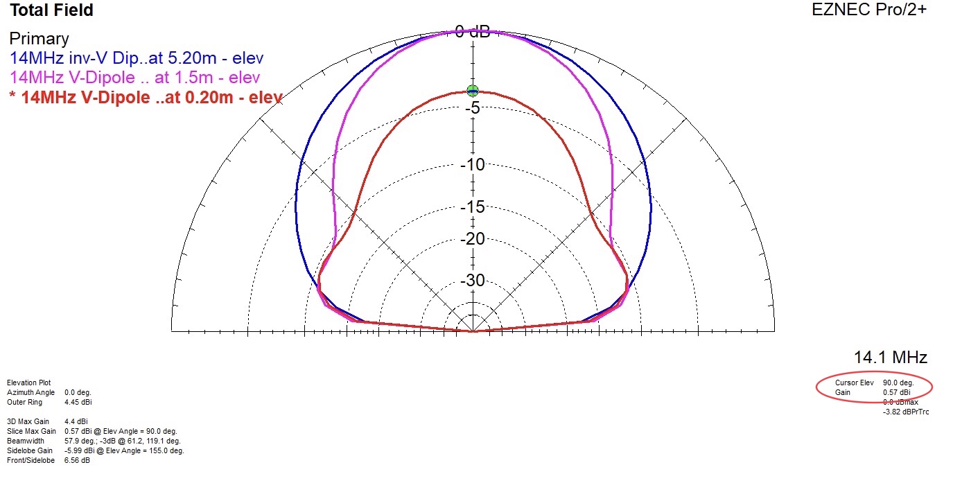
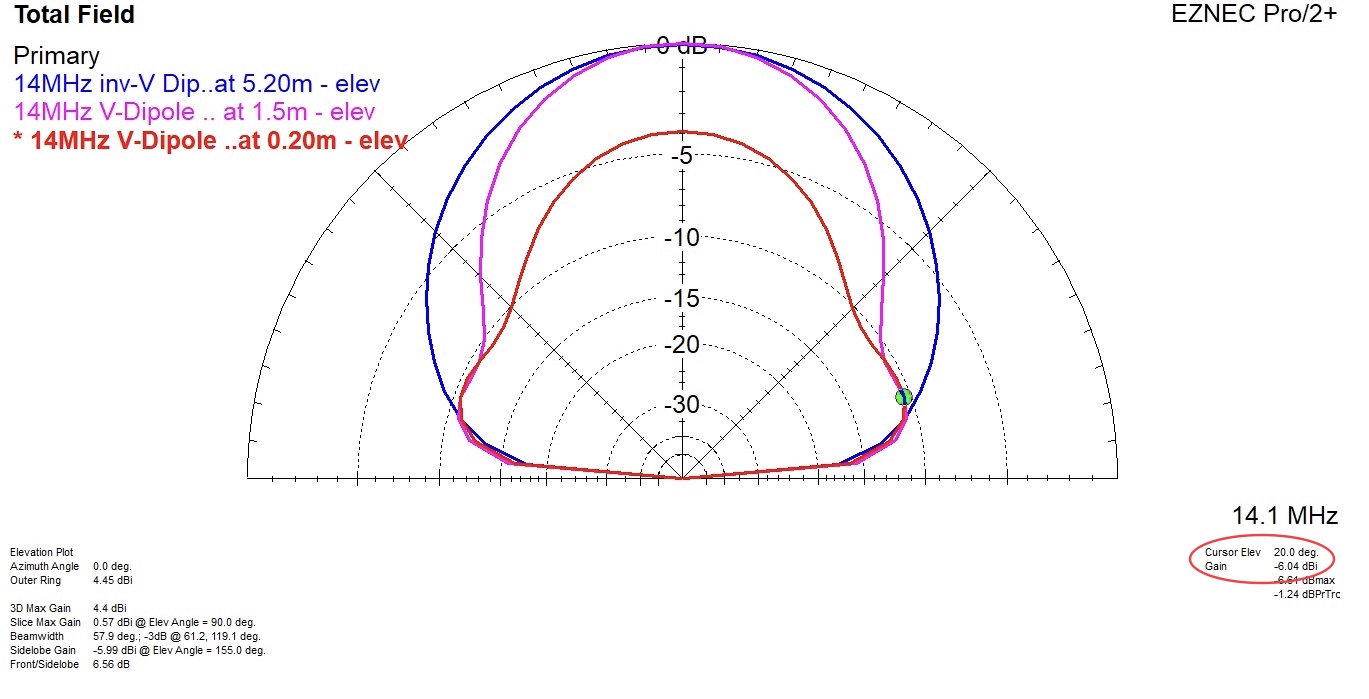
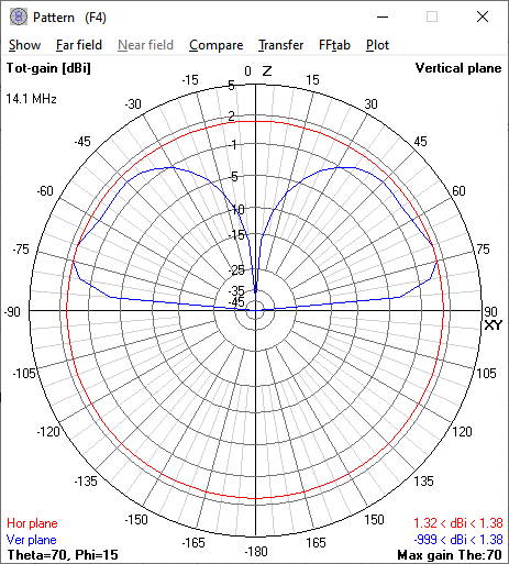
The comparison of a 14 MHz dipole, realized in the geometry variants inv-V and V, provides some information as to where and by how much the radiation properties of the two variants will differ.
If I read that properly, it means that the V at 1.5m is down between 3 and 5 dB for angles from 22.5-45 deg and almost identical to tge inverted-V for 0-22.5 deg.
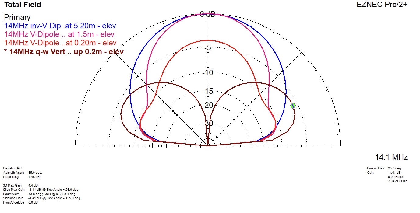
How would it compare to a 1/4 lambda vertical in those directions?
Hi Heinz - thanks for running the model, good to hear it’s not absolutely a dead-end but as I said before, the model doesn’t interest me, I plan to build, tune and try the antenna once the weather improves - it costs nothing - so why not.
I’ll most likely build it for 10m - being the smallest option.
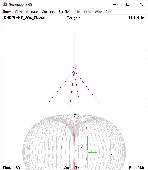
The diagram of a vertical antenna matches my simulations.
Most people assume that a vertical antenna has ideal radiation with an elevation angle of 0 degrees, as shown in figure 1. That’s only true in the open air.
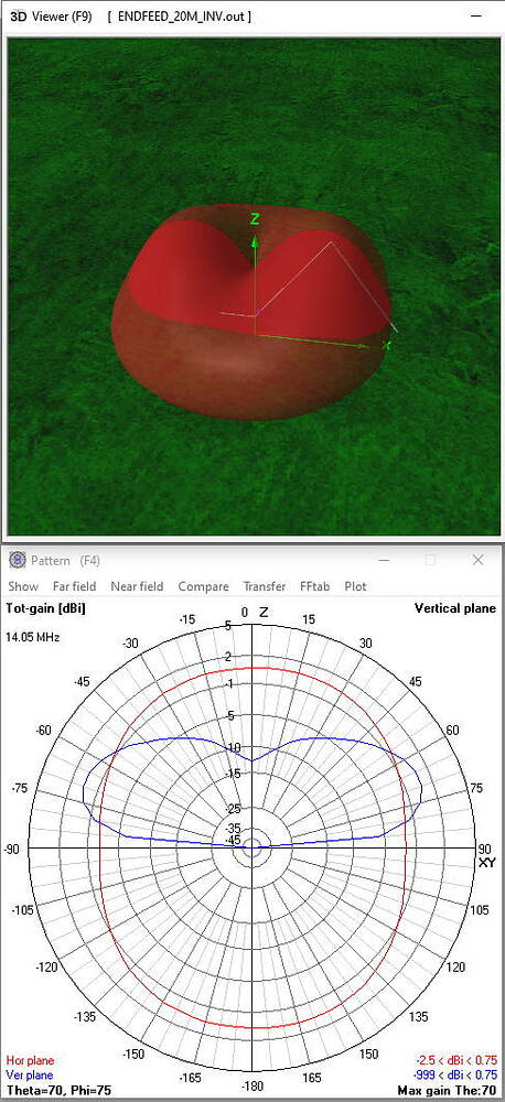
In figure 3 you see a diagram of a inverted v 20m long EFHW. Almost perfect omnidirectional radiation with slight attenuation of approx. 2db in west and east direction. If you consider that the antenna is much easier to install on a summit and works also perfect for 40m, then this antenna is and remains my first choice.
Likewise - with no evidence other than a feeling that it was harder work to qualify my CFHWD seems to be more effective than the end fed one. I use SSB rather than CW which probably makes efficiency more important to qualify. I must admit to being a bit lazy and I usually put the mast up with a 2m j-pole about 50 cm down from the HF antenna and it occurs to me that it would probably have little effect on the centre fed antenna, but that it may well be significant being close ish to the inverted L element of the EFHW. I suspect there are rather a lot of variables involved, some of which are technical ( ground conditions, loss in the feeder, loss in the transformer, propagation, as well as some which are more “social” but might have just as big an effect, time of day ( is anyone chasing ? ), how crowded the summit is and how much space there is to play with, how busy the band is ( trying to compete with a contest station running 1KW to a beam ), if there is just one antenna up or if I’ve been lazy and put two antennas up the same mast as well as the final lazy element for me - do I have to go on another hike to change bands (centre fed) or can I just try the next harmonic without moving… Although I still occasionally use the end fed antenna I have just reconstructed a 40/20/(15)/10 linked dipole with a a 1:1 balun at the top as my main choice as it works at the same time as the 2m antenna up the same pole…
Very interesting reading, but I doubt there will ever be a “best” solution…( Although some will be better than others…). 73. Paul
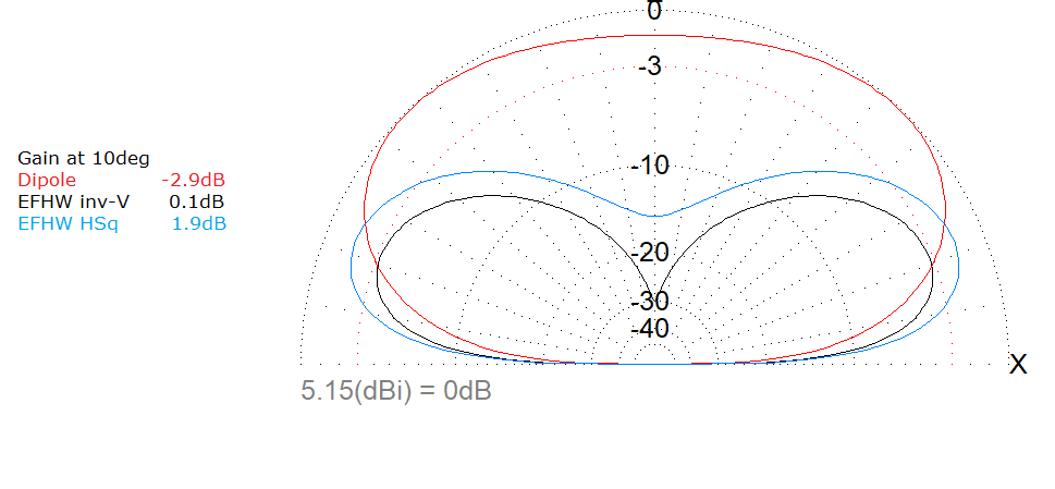
Dipole or EFHW question depends on your objective.
Dipole (red) has greater overall gain of 5.17dB but at 45deg which is great within Europe. For DXing your need to look at low angles around 10deg and here EFHW inv-V (Black) is better by 3db as its gain is 0.1dB.