Inverted Vee Linked Dipole vs. Endfed Antenna (Part 1)

One more mid-life crisis :wink: wisdom:

Learning CW will do much more to the number and distance of DX QSOs than a lifetime of antenna experiments :joy:.

Which does not imply that one couldn’t do both :sunglasses:.

10 Likes

Hi Heinz,

Yes you are right I should be more accurate with my antenna description, sorry.

All models at 14,150MHz

Dipole 20m band
High point of inv-V is at 7mtr and ends are only 1mtr lower. This would be challenge to have ends at 6mtr but putting them lower spoils low angle radiation.

EFHW4010 inv-V wire half-wave length at 40m band
49:1 transformer 2mtr of the ground, wire goes up to 7mtr at half way point and then slopes down to 2 mtr. Transformer has 2mtr counterpoise connected. I think this is easily obtainable setup.

HalfSquare using EFHW4010 as above
49:1 transformer 2mtr of the ground. 5mtr up then 10mtr across and finally 5mtr down. Transformer has 2mtr counterpoise connected. Setup requires two 6mtr masts or mast and a large tree.

I hope this clarifies antenna details. Of course using EFHW4010 on 20m band we use second harmonics (full wave length).

73 Marek

2 Likes

Thanks Marek for clarifying the details.

Just corresponded with questioner Michael@DC8YZ and found out that he actually has a specific idea of an “end-fed” with a small footprint (e.g. something like the Par EndFedz EFT-10/20/40 Trail Friendly).
It’s a pity that he didn’t already write that in his request.
Michael will post the details later.

73, Heinz

Hi Sota Community,
thanks for the many answers and Informations.
Yesterday Heinz HB9BCB asked me follow questions, so i will better Informations about my thougts.

73 Michael

Hello Michael

As you may have read on the SOTA Reflector, there are already some contributions from SOTA colleagues. I don’t know if you can do anything with it, because everyone just describes their antenna (and praises it, hi …) and doesn’t go into the main reason you mentioned about the space requirement.

If we had answers to the following questions, we could certainly give you some more information that also takes your ideas into account.

F1)
Because an end-fed is not an antenna itself, but only describes the location of the feed, it is not clear what you mean by end-fed.
Are you thinking of a wire of random length (random wire) or a dipole for 40/20m (possibly with a link or trap) or a vertical antenna?

Under Endfed I imagine a resonant wire (dipole) i.e. horizontal which can also be extended by an extension coil. Example 40m/20m/10m wire with about 12 longer and then extended by a spool for 40m.

F2)
An end-fed dipole (EFHW) for 40m, for example, is exactly the same length as your linked dipole for 40m. So there would be no space savings.
How high could you hang this end-fed antenna (mast length) and how much space should it take up horizontally?

My portable mast is about 7m high. I would have said about 15m from the space requirement

F3)
Another important point is whether the antenna must have a minimum SWR on the desired bands (is that only 40 and 20m?) for operation without an ATU, or whether an antenna tuner is available?

Operation without a tuner

F4)
Many portable radio operators are, for various reasons, used to the antenna being connected via a coaxial cable and could therefore not imagine the antenna wire and the radials being connected directly to the transceiver.
How do you feel about this?

Connection via an antenna cable to the UNUN e.g. 1:49

I’m essentially concerned with the fact that the power supply ultimately causes losses as a result of the HF transformation, which you don’t have with an inverted vee linking dipole.

The advantage of the power supply is in turn a shorter coax cable since the power supply is close to the ground.

Compared to the linked dipole, you can also change the band with an end-fed one.

That’s my thoughts.

If so understandable I would also post this :slight_smile:

Best regards from Switzerland.

Greetings Michael

3 Likes

Hi, thanks for the clarification - but there are still several questions:

It seems that your primary concern is
a) using a short piece of wire (<10 m?)
b) feed it from one end
c) for multiple bands, namely 40, 20, and 10m.

  1. I am not entirely sure what you mean by ‘resonant’. A monopole radiator or a dipole made from wire is initaelf typically resonant on a series of fractions of the wavelength. But resonance in this sense is not super-important, because you can design a matching circuit that will make sure that the output from your transmitter will see a proper 50 R impedance with no inductive nor capacitative component.

  2. What matters is the efficiency of the antenna, which will depend on several factors, namely the radiation resistance, the ground losses, and, often ignored, the fit of the pattern of radiation at the typical location of usage to the other stations you want to communicate with.

  3. Basically, you can use any piece of conductive material of any geometry as an antenna, even a wet shoestring or the leg of your barbecue table. Even a 50 R resistor is a kind of all-band antenna, albeit a very bad one.

  4. Now, you can use a combination of inductors, capacitors, traps, and mechanical tricks (e.g. folding back a part of the wire) to influence the amplitude and phase of current along your antenna at a given frequency. The best choice will depend on electrical and mechanical aspects (e.g. base loading coil vs. top-hat capacitor).

  5. The frequency-dependent behavior of inductors and traps (typicall LC parallel circuits) can be used to vary that behavior for different bands.

  6. If the antenna is a monopole, you need some other conductive structure so that a current can flow from the transmitter to your antenna. If it is a dipole, you may not need another pole. This depends on where you feed the antenna. For a center-fed antenna, you can split the element in half and use each half as one of the two poles. The split can also happen at other places, but there are dependencies with #4 and #5.

  7. The position of the feedpoint influences the raw feedpoint impedance. If you move the feedpoint along the antenna structure, the impedance will change. This is not a big deal, because you can transform any feedpoint impedance to a pure, resistive impedance of 50R for your transmitter. There may be losses, but not show-stoppers. Some matching techniques will be band-specific (e.g. an L-R match or hairpin match), others can be build in multi-band fashion, like an impedance autotransformer on a toroid.

  8. The extreme in the range of feedpoint position is an end-fed half wave antenna, where either end will work as a feedpoint witn a very high impedance; high enough, that very imperfect conductors in the system, connected to the ground pole of your transmitter, will be sufficien for the antenna to radiate.

  9. Now, you can e.g. build a multi-band EFHW with traps (popular for 40-30-20m), and the inductance of the LC circuit that makes the traps will work like a moderate loading coil and reduce the length of the wire sections that will produce resonance. To a certain degree, you can vary the inductance of each trap and compensate by adjusting the capacitor so that the resonant frequency of the trap remains unchanged.

However, there are limits to how far you can do so, because a trap is optimal only at a certain ratio of L and C. The losses from the trap will grow if you move away from that point for the sale of shorter wire sections.

Also, much more important, by shortening sections of wires, you change
a) the effective length of wire that radiates (the coil will almost not contribute),
and, more importantly,
b) you change the distribution of amplitude and curreny along the combined sections of wire, and this in different ways for different bands.

Now, you can insert additional inductors into the wire segments at your discretion in order to influence that, but the shorter the effective length of the antenna, the more difficult will this become, and the less efficient will the antenna be.

Roughly speaking, antennas down to ca. 50% of the ‘natural’ resonant length can be made with acceptable losses in efficienty, but beyond that point, it will become difficult.

Now, I know some people tried to construct shortened 3-band end-fed half-wave antennas by putting two inductors at carefully chosen lengths, which will then serve as both a means to compensate for the lacking length of wire and as traps for passing only lower frequencies onto the next segment.

I have one of these at home, but have not yet tested it. But I expect that this will
only work well at total lengths > 50% of the resonant EFHW/dipole length for the lowest band.

If you want to go shorter, my gut feeling is that going to a monopole plus some kind of radials, counterpoise, second leg (up-and-outer) will be more effective. The only downside of that path is that the antenna will typically not be resonant across differeny terrain, so you will need a tuner. But a drastically shortened dipole will also be much more prone to detune depending on deployment and terrain (if hanging low).

A long summary of what I learned about antennas in the last seven years :sunglasses:.

Experts - feel free to correct if needed.

73 de Martin, DK3IT

1 Like

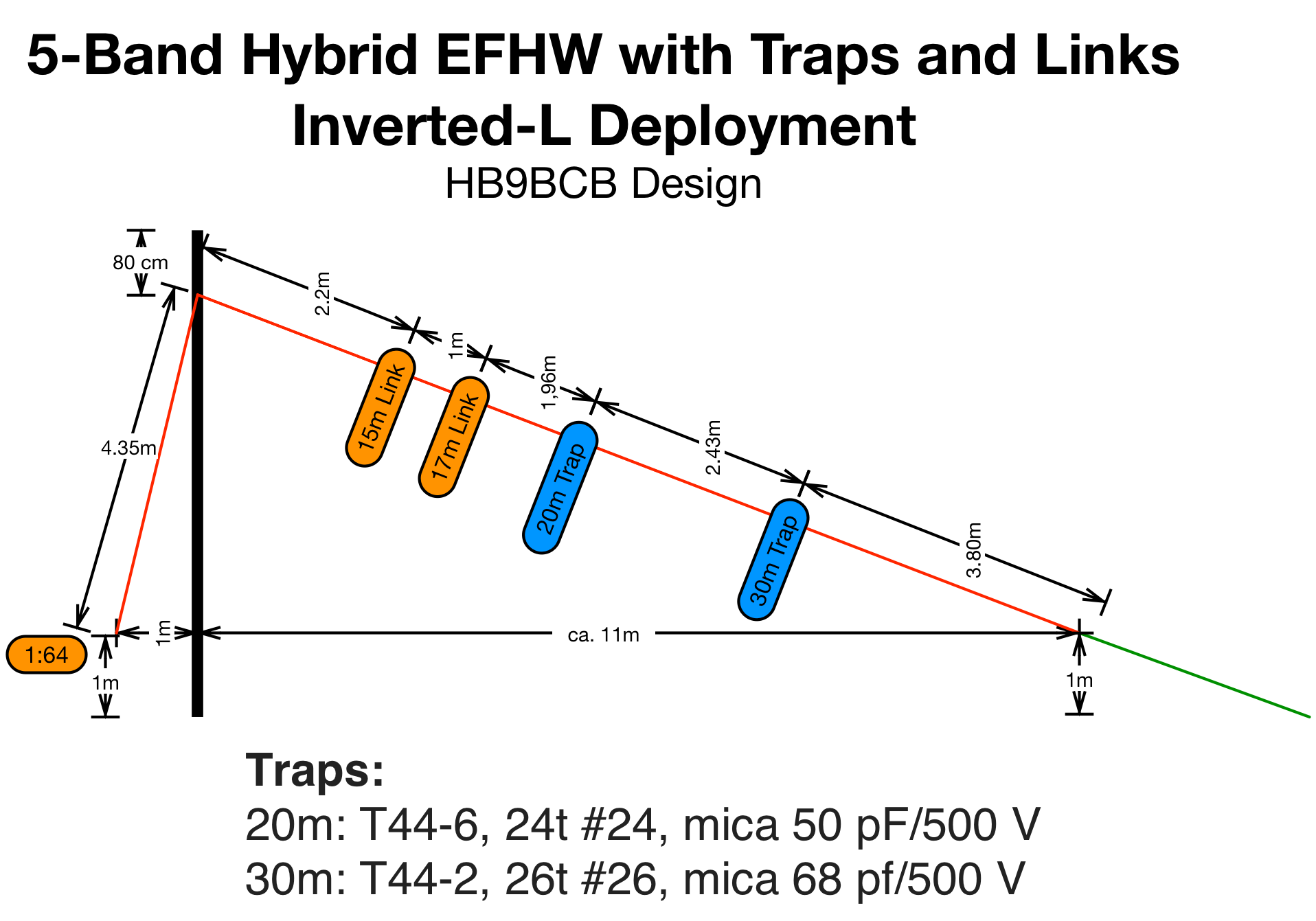
Just realized that you aim at a total length of ca. 15 m. This should work with a variant of @HB9BCB ‘s 3-band design with traps (40-30-20, the 20m should also do okay for 10m) if you increase the inductances a bit and/or add a rather small loading inductor at some clever place. Or just build it for 30-20-10m and design a switchable matching circuit for 40m at the base. Not sure if saving ca. 3m of wire is worth the effort, but this should do the trick.

Edit: Basically, the current design should do the trick with ca. 16m total length.

https://reflector.sota.org.uk/uploads/db9433/original/2X/8/8e47e93f76669f7bca564d38a0ba9ea0be0c7f24.png

For details, please see here:

1 Like

And if 30m is not needed, you could try to copy this shortened EFHW for 40-20-10m with a loading coil and a total wire length of ca 12m:

https://www.wireantennas.co.uk/hf/10m?product_id=138?product_id=138

Edit: If you vary the inductance and position of the coil a bit and control the self-resonant frequency properly, the coil could serve as a trap for 20 and 10m and as a loading coil for 40m.

Maybe one of the antenna experts in here can propose details for that inductor and its position.

2 Likes

If it’s ignored by most SOTA activators it’s not out of ignorance but because chasers are located typically at many compass bearings, which favours an antenna with an omnidirectional radiation pattern.

If I’m doing, for example, the transatlantic S2S weekend event I’ll choose a summit where I can align my dipole lobes with the great circular route for that region but otherwise the antenna orientation doesn’t matter much for general SOTA activations, especially when I’m working lower HF bands for country & regional contacts followed by higher HF bands for intercontinental Dx.

Furthermore, although some of the SOTA summits have nice, uncluttered, grassy [even flat] tops where I can position the antenna how I like, the majority are very rocky, lumpy summits often with several false summits which limits how I can orientate the wire antenna near my operating position in a sheltered spot out of the wind & rain. I’m sure many others have this problem.

At the risk of repeating what I said above, given the many confounding variables when operating from mountain tops, some of the discussion about optimizing the antenna design seems to me to be diminishing return on effort or indeed running contrary to practical considerations ‘in the field’.

73 Andy

2 Likes

Martin,

Strictly speaking, this drawing does not correspond exactly to my antenna. The length specifications are slightly different (my antenna is approx. 1m longer) and my deployement was even more like an inv-V - so to be correct, the label on this drawing shouldn’t read “HB9BCB Design”, but maybe “based on HB9BCB design”

If I remember correctly, you made this drawing for your contribution to QRP ARCI some time ago?

2 Likes

What I mainly meant was not so much directionality in compass bearings but variations in take-off angle, resp. the distribution of radiation by angle, because this will influence the first hop distance (or better: the distribution of signal strength along that axis), so it is really hard to tell which one of two antennas will be better just by their overall efficiency. As long as potential chasers are available in all directions and within a wide range of distances, as typical for summits in the Alps, it may not matter much in practice.

After all, we essentially want enough QSOs with random fellows from the SOTA community. We do not need to establish a communications channel with a predefined target station.

We are in agreement, by the way: Any reasonable antenna will work for SOTA, at least in central Europe. Other regions might require a more careful choice so that your call for a contact falls within habitated land :sunglasses:.

1 Like

Dear Heinz,
you are right, it should read ‚based on a design by HB9BCB‘. Back then, I simply wanted to give proper credit (and if I remember correctly, the additional links and the tuning for inverted-L deployment were at least inspired by our discussions back then). Hope this is fine with you.
73 de Martin, DK3IT

2 Likes

Good Morning Martin and Heinz,

thanks for your great explanation and Infos.

For me it would be interesting to compare how the efficiency of the power fed in and the power delivered behaves in relation to the HF transformation. so from the losses.

Linked DIpol with Inverted Vee with approx. 15m cable

Or end-fed antenna with 5m cable

Michael

Dear Michael:
With this information alone, nobody can tell. There are just too many variables.

If you are speaking of the losses just of the feeding mechanism of two otherwise identical half-wave dipoles:

a) for a center-fed dipole, it is mainly the feedline loss, which depends on the length and type of feedline (in dB/100m from the datasheet), e.g. RG174 vs. RG58.
b) for the end-fed, it depends on the design of the matching circuit. A well-designed autotransformer can reach ca. 85+% efficiency, poor designs or poor builds less than 25%.

Both will also have additional losses if there is an impedance mismatch.

If built properly and deployed in identical set-ups, an end-fed vs. a center-fed dipole will behave so similarly in practice that no receiving station will be able to distinguish.

If you are talking of completely different antennas, it is just impossible to make a valid statement because of too many variables.

The differences between most popular SOTA antenna designs are less than ca. 6 dB (typically much less, if we leave out flawed designs or very short ones). Even this is hardly relevant in S-levels, although 6 dB (= one S-level) less means a 75% weaker signal (10^(-0.6) = ca. 0.25).

HB9SOTA did a substantial comparison of SOTA antennas in a field test back in 2017:

For most antennas tested, the difference was less than 0.5 S-levels.

That is all one can say at this level of abstraction. You can built and try - and this is what many hams consider an essential part of the fun. But since the outcome will depend on multiple variables (see above), such a single comparison will also be just of anecdotal value.

1 Like

6dB is not 75%

6dB is 4 times in power or 2 times in voltage

so 25% in power and 50% in voltage

1 Like

I may be wrong, but 6 dB less means minus 6dB, which is 1/4=25%of the baseline, and in terms of signal-to-noise ratio under otherwise identical conditions a loss of 75% (relative to 100%).

Or am I missing something?

1 Like

Sorry, I misunderstand you.

Yes, 4 times less in power is 75% loss

1 Like

Agreed, 6 dB loss is commonly understood as

  • 10^(-6/10)•100% in power

  • 10^(-6/20)•100% in voltage

2 Likes

Michael,

It is indeed as Martin briefly summarized above.
It’s understandable that one is primarily concerned with something that one can see and hold in one’s hands and not with all that is hidden.

With the mechanically as short as possible antenna you are aiming for limited space (in your case typically for densely overgrown/wooded hills), one would have to worry above all about the influence of the antenna properties by objects that are all around at a distance of less than lambda/2.

A very hidden and therefore often overlooked, not exactly complex, but for various reasons very difficult to record influencing factor also has an effect in the above cases from the following facts:

  • In the bark of shrubs and trees, water flows only in the summer months, not in the winter months. The attenuation of radio waves is therefore greater in the summer months
  • Dead trees do not attenuate radio waves to the same extent as healthy ones. In the case of infested trees that are not yet dead but diseased by bark beetle larvae, their sex, age, number and distribution per meter must be taken into account
  • Experience has shown that this influencing factor is particularly noticeable on April 1st. :sweat_smile:

Free tip
Simply realize a few hundred SOTA activations with a few tens of thousands of QSOs and don’t think that when particularly special events occur, you can/must explain quickly the cause of them, because there are usually too many unknown factors for that.

73 gl, Heinz

2 Likes

Or, scientifically: If you want to understand causal effects, you have to
a) control, in a randomized fashion, a single variable that we assume causes some effect,
b) keep all other variables as equal as possible (“ceteris paribus”);
c) measure and repeat the measurement often and trying to avoid any pattern in the timing of the measurements/experiments (otherwise, if you always go to the pub on Saturday nights, and your friend Joe does the same, you might assume that Joe is spending all of his life in the pub).

While we sometimes have to accept a compromise, the above is a good and practical guideline - e.g., it is better to run two WSPR beacons in parallel than to do sequential antenna tests.

Also, the better you can isolate aspects of your model, the more you will be able to discover.

For instance, measuring the efficiency of a broadband transformer with the setup described by Owen Duffy (and explained very well by Heinz in this forum) is better than using two transformers back-to-back, which in turn is still better than assessing a complete antenna system by the number of QSOs.

In these sad times of alternative “facts”, esoterics, and clickbait journalism, we as radio amateurs could and should evangelize the ideas and keep alive the torch gifted to us by the heroes from the age of enlightenment; of which some paid their insights with their lives…

2 Likes

Simultaneously testing two antennas using synchronised WSPR transmissions, when done carefully, can give excellent results. It’s important to get lots of data though. Hundreds of data points are needed for anything useful to be concluded when the potential differences are small.

3 Likes