To me it sounds like there is more noise on the FT 817…
Why don’t you use the transverter mode on the KX2 to get displayed the correct frequency ?
What is your experience with the TCXO…has it improved a lot? I still haven’t installed mine - I’m just rebuilding my shack. So many projects … (for me it’s kind of typical for the Christmas season)
Yes Armin, the transverter seems to have less noise.
But I am not yet satisfied with the large signal behavior. I have provided two anti-parallel protection diodes at the 28mhz input of the converter because the RF VOX activates the attenuator after a few milliseconds delay. I will replace the diodes with 2 BA70-04 with 2 diodes each in series. This should improves the IM3.
You don’t have the problem if you use the PPT output of the KX2. But then you have to make a secure connection, otherwise you will destroy the FET from the preamplifier.
Since I am sometimes very excited when activating, I chose the safe solution with the RF Vox. The circuit itself has proven itself and the RF VOX is hardly noticeable: DL1CR Test RF Vox transverter - YouTube
The TCXO works very well. No noticeable drive and the offset is less the 10Hz. The offset of the original XO is -400Hz and drifting up to +100Hz, when the transverter warms up.
Just an idea … I did not try this (yet).
Connect the microphone to the transverter and tap the PTT there, then connect to the KX2.
Put the KX2 in TX after a short delay, so making a “mini-sequencer”.
When the microphone gets broken or disconnected, you will be sure nothing will happen (unless of course, the connecting lead gets shorted somewhere and puts the TX in continous transmit …).
Attenuator should kick in instantly, but have a short delay switching off, because the tail of the TX could still cause some trouble …
Anyone tried it this way ?
I haven’t done that, but in essence It’s the “right” way to do it. Avoids hot switching anything. Without rf everything else can be switched over in almost any order and if the rf is last to go on and first to go off, the relays are protected. It’s the best option when using transverters, high power amplifiers and mast head amplifiers. The alternative is a complete sequencer driven by the microphone PTT.
The option often used, keying the driver radio and letting its rf switch everything else, provides less protection for hot switching relays.
Your suggested method only lacks a method of forming the transverter off after the rf from the kx2 has been terminated.
Ian White GM3SEK published an alternative two step sequencer in the RSGB handbook some years back. With revision to suit solid state voltages it is quite suitable for today’s needs.
Hi Andrew,
I bring this thread up, because a friend of mine develops a commercial board for the rx/tx switching.
You are right, after the first ~10ms transmitting time with max.1 W the swr of the kx2 goes quick up, because driving the protection diodes. I guess, the power goes down, and than the relay is switched.
I measured this with my digital scope, but forgot the details. The relay is switched with less then 0.15A rms rf current.
73 Chris
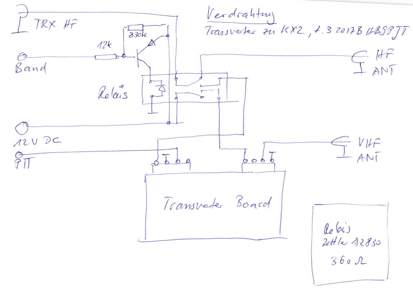
I use the PTT from KX2 and also the “transverter signal” which I programmed for 2 m and which is from an output of the Elecraft KXIO2. I do not use an attenuator, because the lowest output power of 100 mW in transverter mode can be configured by the KX2 and is sufficient for the transverter. This operation is absolutely safe with this configuration, even from misoperation. My transverter has one VHF and one HF output. With this configuration it switches on automatically as soon as I select the 2m band on the KX2, otherwise the HF output is active.
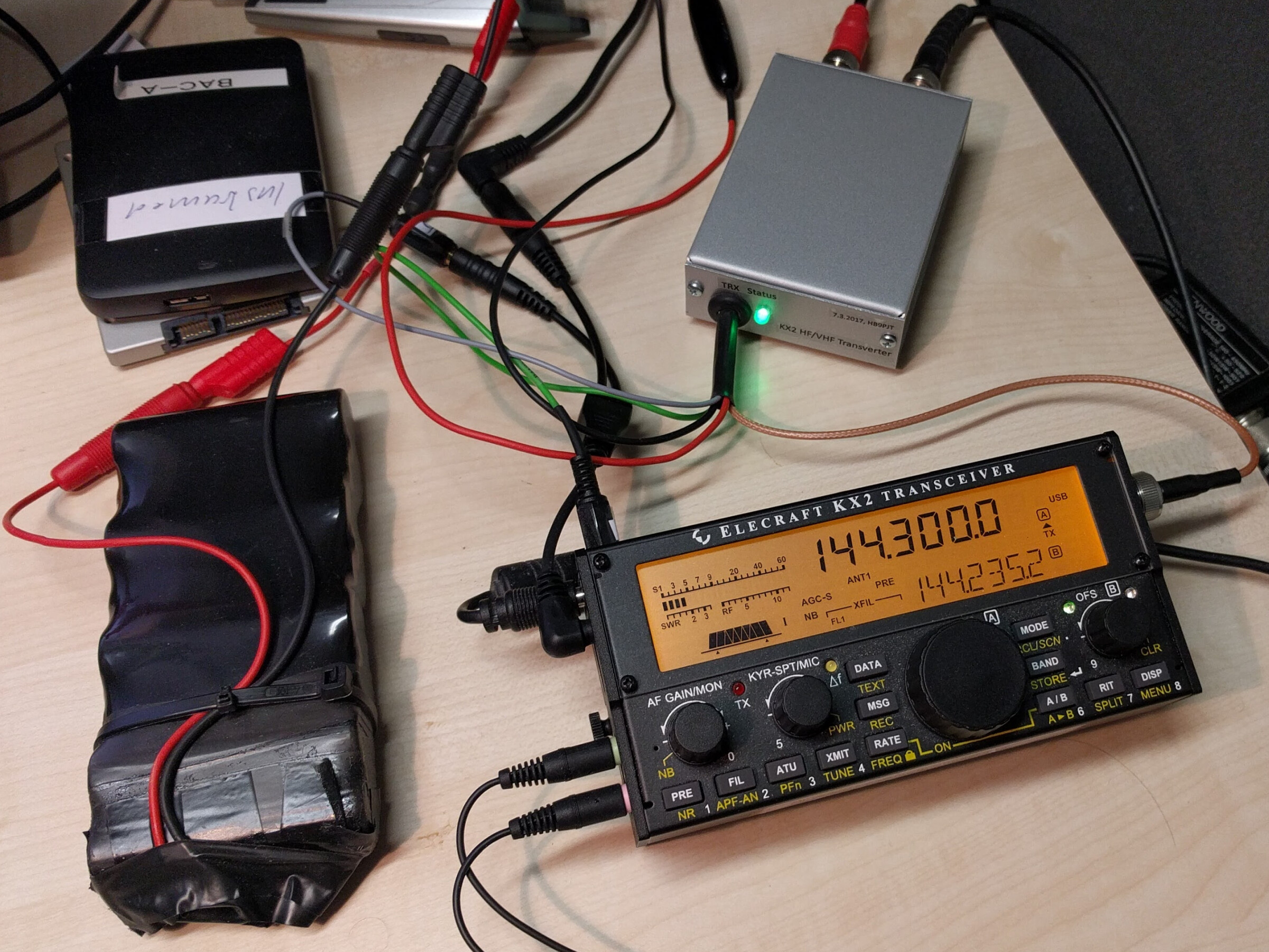
Six years on, Chris DL1CR pointed me to this thread. Below is my 28 and 144MHz homebrew transceiver project from around 2021 (lockdown project).
Because I built the exciter I had the opportunity to take RF drive before the PA. So I didnt need to use much attenuation.
My transverter (and the homebrew 28MHz SSB monoband transceiver) performed well (although the TCXO mod would have addressed a few hundred Hz drift on switch-on) and I discovered what a great band 2m SSB is for hilltop portable work. Always someone monitoring 144.1 SSB.
SP-8: a homebrew 28MHz SSB transceiver for a UR3LMZ 144MHz transverter | VK3HN
I always assumed that Alex UR3LMZ no longer offers the transverters. By chance, I saw today that his transverters are available on eBay.
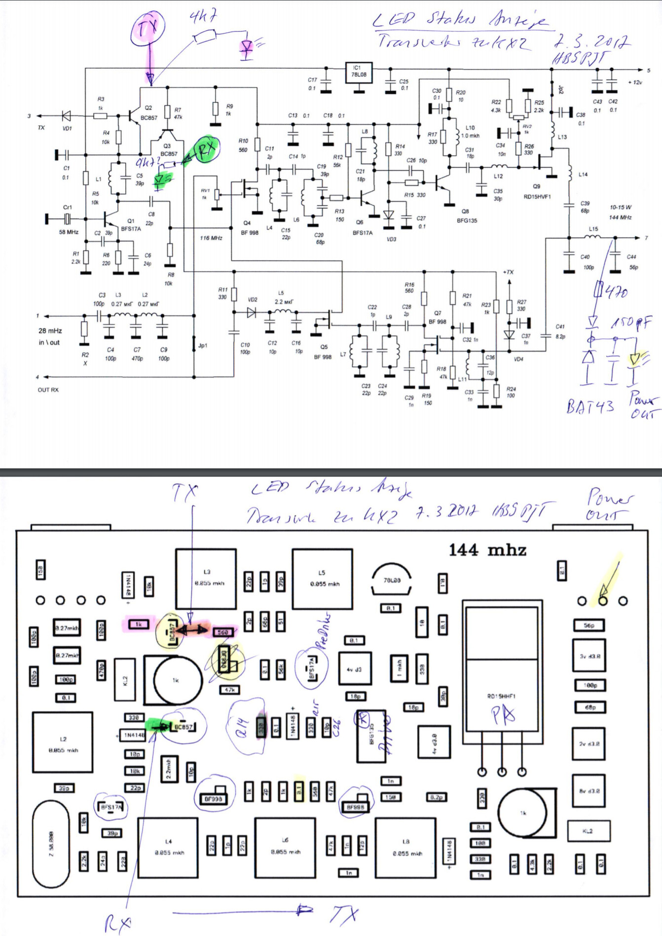
AliExpress also offers the RD15HVF1 VHF/UHF FETs at a very reasonable price. I would prefer used ones, they were probably removed from obsolete GSM stations. Take care of fakes.
73 Chris