Homebrew 144/28 MHz Transverter

Anybody besides me get a “403” error on the transverter store web site? I guess that is not quite as serious as a 404? :slight_smile:

If anyone is interested, I asked Serge, UT5JCW why his web site does not work for VK. He says it’s deliberately geo-blocked, as he is not interested in doing business with us. Our reputation precedes us, apparently :slight_smile:

Well, 404 is “not found” but 403 is “found but you aren’t allowed to look at it” which is fairly enticing…

It’s you John or it’s fixed. i.e. works for me.

I guess a typo created “HF vox” instead of “RF vox”, ie. RF actuated PTT?

Very nice transverter build.

73 Andrew VK1DA/VK2UH

I think it’s just the German for “RF vox”

Right Andy.

HF - HoeheFrequenz (High Frequency) often used when in English you could use RF Radio Frequency.

Another “False Friend” between the two languages in abreviations - KW can mean Kilowatt - bit it can also mean “Kuerzewelle” which in English is Short Wave.

73 Ed.

Hi Luc,
I set the power on my KX2 on 28MHz down to 0.5 Watt. After the 20dB attenuator it’s 5mW. That’s more then enough and therefore I set the tx gain on the transverter board to 50%. So I get the output power of 10W at 12.8V.

A rx signal of 5uV = S9 at 144Mhz produce a S8 on my KX2 at 28MHz.

I did not messure the rx noise level of the transverter yet.

73 Chris

Matching my transverter I put a rabbit ears dipole on a carbon fiber pole.

Legendary 0dbd gain and 2db coaxial loss according to my motto “Less power - more fun”

73 Chris

I measured the sensitivity of the transverter today. The following video shows the equipment and the process. DL1CR S/N test 10m 2m transverter - YouTube

With an input voltage of 0.05uV the signal-to-noise ratio is approx. 10dB (see picture).
The results could be somewhat worse with the usual measurement methods. In direct comparison with my Yaesu FT-817, the transverter was equivalent.

73 Chris

Love that little rotary attenuator :slight_smile:

Me too. It works up to 5Ghz.
A friend gave it to me on loan 4 years ago. I hope he doesn’t miss it.
73 Chris

1 Like

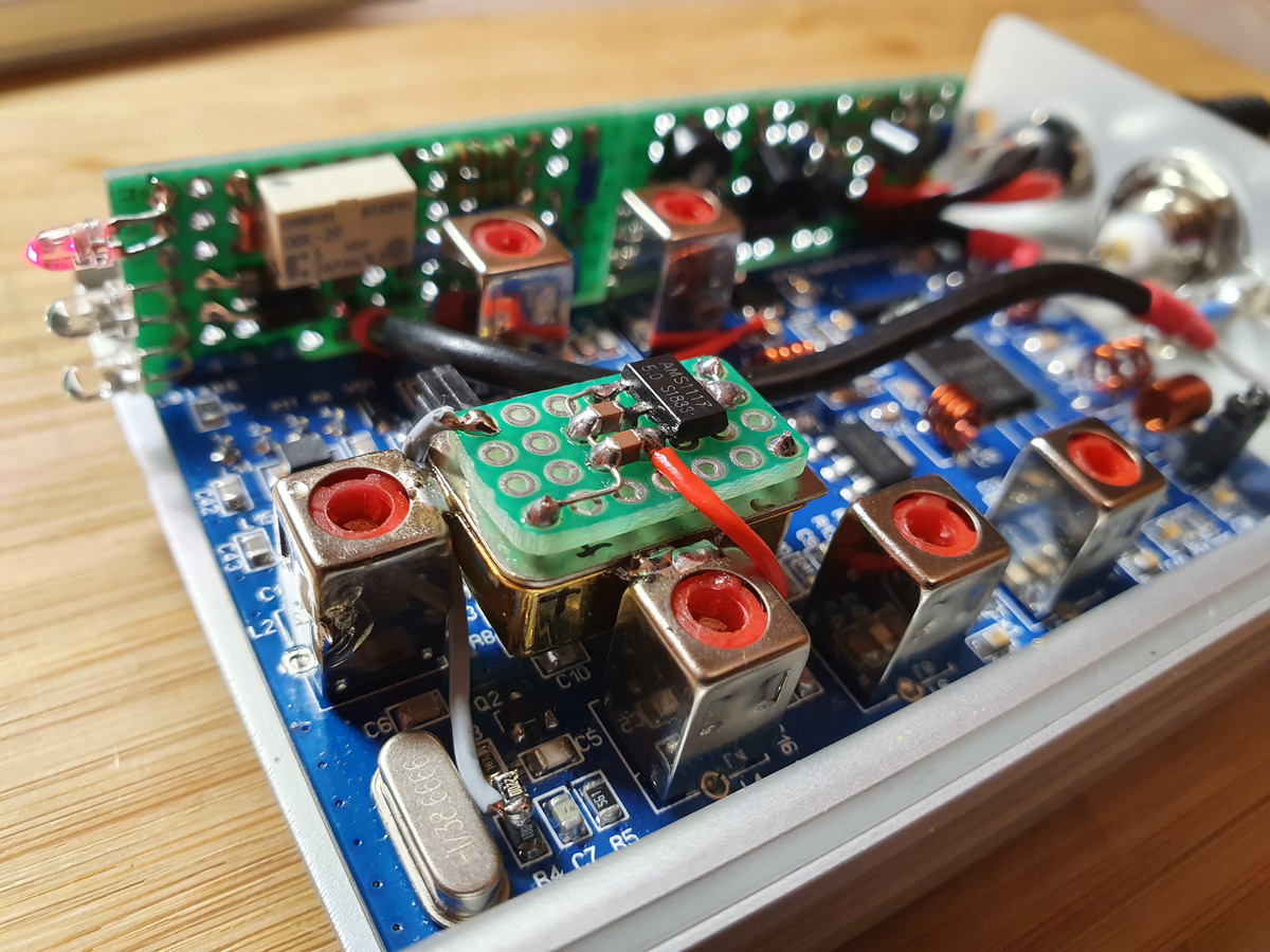
I converted the transverter to operate with a TCXO. The TXCO comes from a finished circuit board.
Armin made the suggestion.

I only used the 116 MHz chip and voltage regulator. The originally installed quartz can remain in the circuit. It is important that the 100p capacitor and the 220Ohm resistor are installed as close as possible to the transverter board. Here, SMD components are absolutely preferable (see picture).

73 Chris


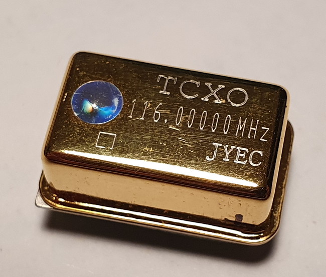
[https://www.ebay.de/itm/116MHZ-hifi-TCXO-0-1ppm-Ultra-precision-golden-Oscillator-Clock-on-power-supply/133261062748]).

73 Chris

1 Like

today I was able to compare the noise behavior of the transverter on the KX2 with the FT817 with CW filter. The beacon DBOTHE as a reference is approx. 100km away.


73 Chris
1 Like

Hey Chris

To me it sounds like there is more noise on the FT 817…
Why don’t you use the transverter mode on the KX2 to get displayed the correct frequency ?
What is your experience with the TCXO…has it improved a lot? I still haven’t installed mine - I’m just rebuilding my shack. So many projects … (for me it’s kind of typical for the Christmas season)

73 Armin

Yes Armin, the transverter seems to have less noise.

But I am not yet satisfied with the large signal behavior. I have provided two anti-parallel protection diodes at the 28mhz input of the converter because the RF VOX activates the attenuator after a few milliseconds delay. I will replace the diodes with 2 BA70-04 with 2 diodes each in series. This should improves the IM3.

You don’t have the problem if you use the PPT output of the KX2. But then you have to make a secure connection, otherwise you will destroy the FET from the preamplifier.

Since I am sometimes very excited when activating, I chose the safe solution with the RF Vox. The circuit itself has proven itself and the RF VOX is hardly noticeable: DL1CR Test RF Vox transverter - YouTube

The TCXO works very well. No noticeable drive and the offset is less the 10Hz. The offset of the original XO is -400Hz and drifting up to +100Hz, when the transverter warms up.

Good luck with the handicrafts.

73 Chris

Just an idea … I did not try this (yet).
Connect the microphone to the transverter and tap the PTT there, then connect to the KX2.
Put the KX2 in TX after a short delay, so making a “mini-sequencer”.
When the microphone gets broken or disconnected, you will be sure nothing will happen (unless of course, the connecting lead gets shorted somewhere and puts the TX in continous transmit …).
Attenuator should kick in instantly, but have a short delay switching off, because the tail of the TX could still cause some trouble …
Anyone tried it this way ?

Luc ON7DQ

Luc, that’s an interesting solution.
But you must consider that in the transverter the high level of the PTT circuit is 8V, of the KX2 3.3V.

73 Chris

I haven’t done that, but in essence It’s the “right” way to do it. Avoids hot switching anything. Without rf everything else can be switched over in almost any order and if the rf is last to go on and first to go off, the relays are protected. It’s the best option when using transverters, high power amplifiers and mast head amplifiers. The alternative is a complete sequencer driven by the microphone PTT.

The option often used, keying the driver radio and letting its rf switch everything else, provides less protection for hot switching relays.

Your suggested method only lacks a method of forming the transverter off after the rf from the kx2 has been terminated.

Ian White GM3SEK published an alternative two step sequencer in the RSGB handbook some years back. With revision to suit solid state voltages it is quite suitable for today’s needs.

73 Andrew VK1DA/VK2UH

Hi Andrew,
I bring this thread up, because a friend of mine develops a commercial board for the rx/tx switching.

You are right, after the first ~10ms transmitting time with max.1 W the swr of the kx2 goes quick up, because driving the protection diodes. I guess, the power goes down, and than the relay is switched.

I measured this with my digital scope, but forgot the details. The relay is switched with less then 0.15A rms rf current.
73 Chris

I use the PTT from KX2 and also the “transverter signal” which I programmed for 2 m and which is from an output of the Elecraft KXIO2. I do not use an attenuator, because the lowest output power of 100 mW in transverter mode can be configured by the KX2 and is sufficient for the transverter. This operation is absolutely safe with this configuration, even from misoperation. My transverter has one VHF and one HF output. With this configuration it switches on automatically as soon as I select the 2m band on the KX2, otherwise the HF output is active.

73, Peter - HB9PJT


2 Likes