There are also professional devices with IRF transistors. For example the Q-MAC transceiver, which has 2 pcs. IRF830 in the PA, but with 50 volt supply.
73, Peter - HB9PJT
There are also professional devices with IRF transistors. For example the Q-MAC transceiver, which has 2 pcs. IRF830 in the PA, but with 50 volt supply.
73, Peter - HB9PJT
I have exactly the same issue. If I switch the amp off so that it is bypassed, the built in SWR bridge says 1:1 If I switch the amp on, it says 1.5:1 into the same load. There is definitely something strange with the SWR measuring circuitry. If I switch it into unlimited mode it says NL mode on, but it doesn’t go into unlimited mode (V1.9 firmware) The amp is pretty well useless to me as with a portable aerial SWR of 1.5:1 (Not unreasonable) it just trips out because it sees an SWR of 2:1. I would like to know if anyone has a fix for this.
If it worked reliably, this would be a great amp, giving over 40 Watts from a very small box. The build quality looks excellent. I use loaded verticals for /P operation. I have a matching network at the feed point, and tune with an antenna analyser before connecting the amp. I still struggle with this amp.
Some questions arising from your measurements. Does the SWR into a known good load change from amp on to amp off, and does the poor swr when indicated vary with frequency band? eg is it poor on 10m but ok on 80m?
Can you see the type of coaxial cable connecting the switch (amp on/off) to the input and output of the amplifier? or is it done with PCB traces… and is the swr detection circuit in use whether the amp is On or Off?
The way that switching has been done, and the method of connecting to the amplifier board could all make a big difference to the SWR performance of the amplifier.
73 Andrew VK1DA/VK2DA
The SWR anomaly is still there even into a Bird Termaline 50 Ohm load. It is reasonably consistant over all of the HF bands, testing into the dummy load. The radio driving the amp agrees that the dummy load is a good match when operated with the amp off. The connectors on the amp are soldered directly to the PCB. The RX / TX switching is performed by a relay right next to the connectors. I did suspect the relay at first, but as the SWR circuit willl be on the aerial side of the relay, that is probably not the cause.
PM me when you are ready to sell it.
I am going to fix it! lol
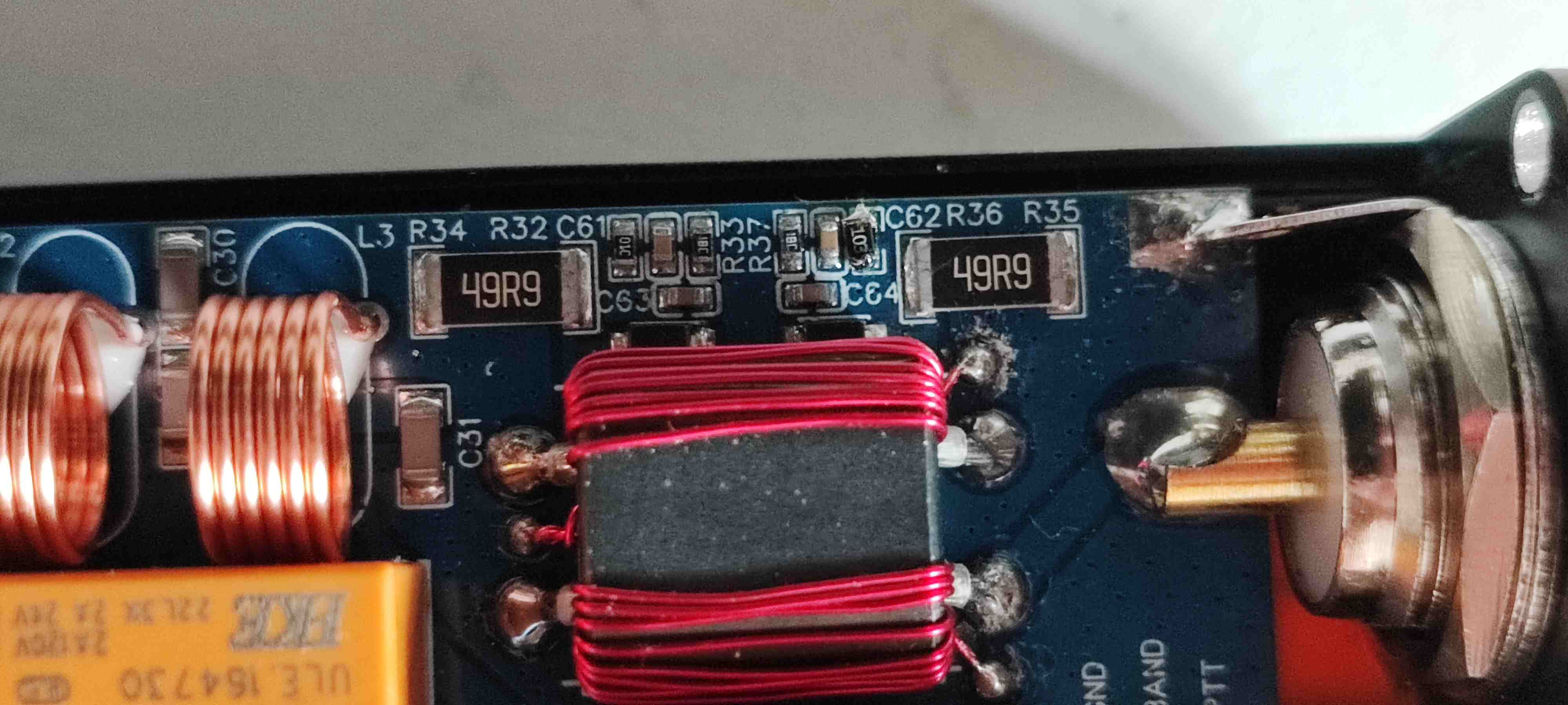
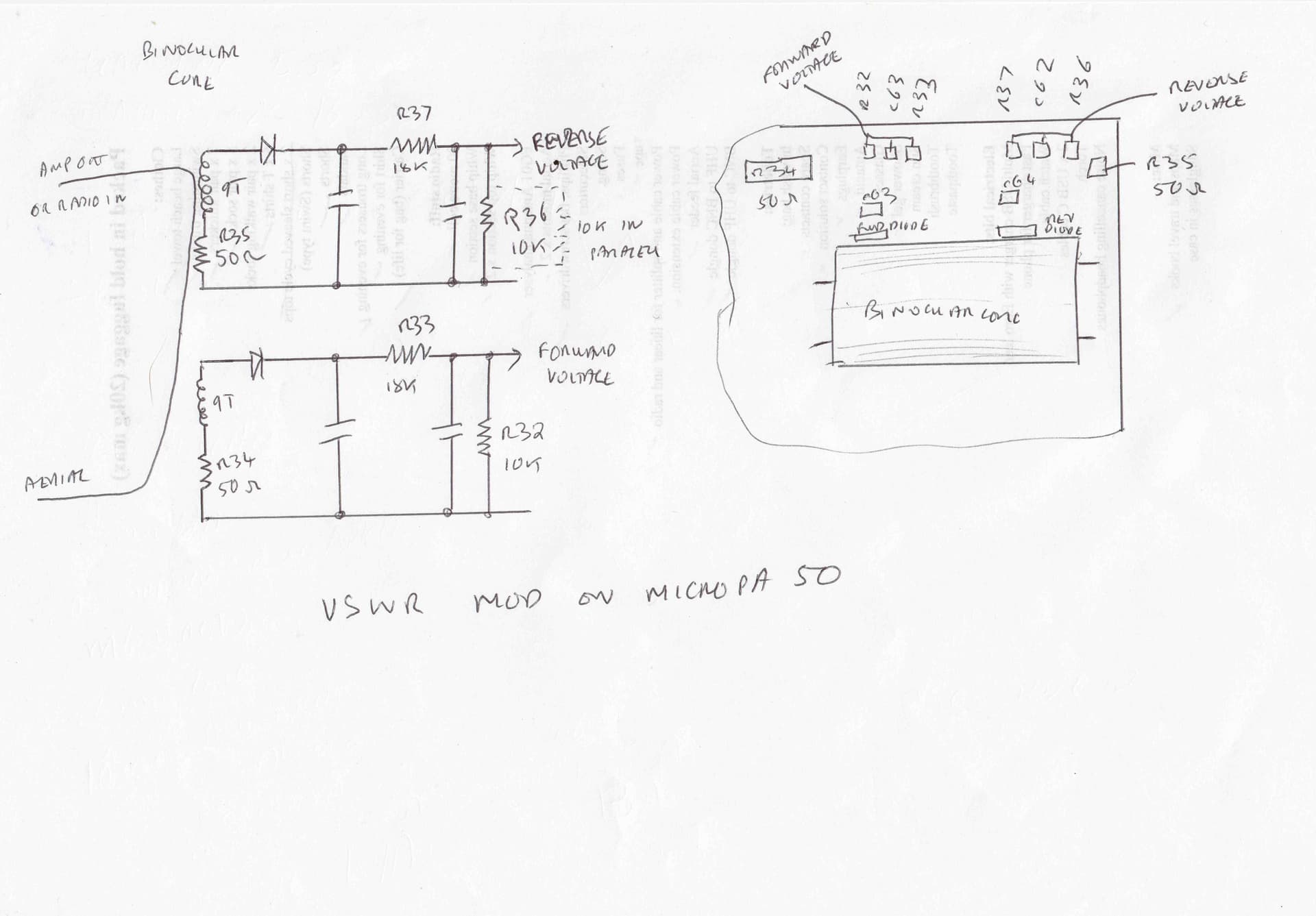
I think I may have fixed this. Having done some measurements, the measured SWR seems higher than it should be. It seems OK at low power settings, but gets progressively more pessimistic as the power increases. This effect also seems to be worse at higher frequencies. The SWR measuring circuit is simple and pretty standard, being a binocular core with 9 turns to sniff off forward and reflected voltages. These voltages are then rectified by diodes and fed to a voltage divider (R33 and R32 for forward, R37 and R36 for reverse) R36 and R32 are 10k surface mount. Looking at my measureents, I reckon that halving R36 to halve the reverse voltage this would give the required result. I soldered another 10k surface mount resistor across R36. The SWR protection still works, but is now less sensitive.
Try this at your own (Great) risk! It seems to be a workaround at the moment. I only use resonant aerials that are pre tuned using an analyser, so the SWR protection is not that important to me. Not a sensible mod if your amp regularly sees a mismatch. You could easily end up blowing the output FETs. However, at least I can now use my amp.
I would be interested to hear other people’s experiences in the field.
Just as I thought. I guessed you would have to do something like that back when these amps were first mentioned.
You sir, are a gentleman and a scholar. I’m going to try this when I get home from work today!
Does the IRF 830 have the same characteristics as a 530 with just bigger power handling? I’m not sure if transistors designed for RF output stages are more robust or not. I just know that the 530 was chosen in this particular design because of its ubiquity. They’re cheap and available but mostly designed for switching applications. They tend to be less linear than other part numbers, but maybe that’s not really a problem for this application. FWIW, at HF frequencies it seems like pretty much any part number oughta work. It’s peculiar that there isn’t something better than this floating around out there.
To see the differences between IRF530 and IRF830, check the data sheets on the web. Both types are low cost switching transistors for less than 1 USD each.
IRF530 14A 100V N-Channel Power MOSFET
IRF830 4.5A 500V N-Channel Power MOSFET
73, Peter - HB9PJT
Other FETs used in amplifiers include the Mitsubishi RD16HHF1 rated at 16w each, so a push pull pair would produce 32w in ideal conditions and would go higher in frequency, up to 50 MHz. There are higher powered devices in the series.
Earlier devices were the MRF475, 12w and its driver MRF476. Motorola application design note AN779. Communications Concepts produced kits for amplifiers at various power levels, but the lower powered kits don’t seem to be available. Or some parts are unobtanium.
Other amps include the Hard Rock amplifier and the HF Projects amplifiers. Neither of those are as affordable as the Chinese amps, but they may perform somewhat better. Depends on whether you want a project or a product.
73 Andrew VK1DA/VK2DA
Are you sure it’s 10k? The markings on R36 clearly say 49.9 ohms and that’s a value that makes a lot more sense for an SWR circuit. Am I misunderstanding something?
Due to the tiny components and lack of space, the silk screening of component numbers is not right next to the components themselves. The 49.9 Ohm resistors are the terminating resistors, R34 for forward and R35 for reverse. Here is a photo of my modification and my traced out circuit. The extra 10k has been added across R36, which is the tiny surface mount resistor next to the 49.9 Ohm R35. (You can just make out my dodgy soldering in the photo!) Let me know how you get on.
Mine just arrived - 8 days from CN to delivery point is pretty good !
I’ll give it a good test and update with my findings
Cheers
Rick
I will be interested to see how you get on with it using real world aerials. I have been testing mine out today with my SWR mod and it now works perfectly into all of my portable aerials on all bands. The SWR protection still works, but is far less sensitive.
Hi, I’m going to make a fix with the additional resistor and check it your solution. Right now I’m not able to use my amp ![]() I hope it helps more to fix the SWR otherwise he will be sold…
I hope it helps more to fix the SWR otherwise he will be sold…
It worked for me. It just makes the reverse power detection less sensitive. It offers less protection, but I have run it into all sorts of mismatches and it has survived, with the protection cutting in where appropriate. I can now use the amp, which I couldn’t do before.
Hi Barry
Yep, similar effects with mine here on test
With a 1:1 SWR (dummy load) at 25W the amp reads 1:1.02 - not bad at all
With a 1.5:1 SWR (75 ohm resistive load) at 25W the amp reads 1.6:1 so that’s not too bad either
With a real antenna and an SWR of 1.2 on 20M the amp reads 1.45:1
With a real antenna and an SWR of 1.6 on 15M the amp reads 2.1:1 and shuts down
I suspect the part of the problem is that it’s overreacting (duh) to reactive loads rather than straight resistive ones. Even worse, I can’t even use an auto tuner with it as it shuts off during the tuning process !
I will do the mod for sure, thanks for the input on this
Cheers
Rick
OK, mod done … with good results
I think the SWR is now reading close to the real values, though of course it still gets sniffy at 2:1
I replaced the 10K resistor with a 4K7 one - a “massive” 603 size as that’s what I had in stock.
Feeding it with 2.5W from the FT-817 gives 30W PEP output measured on my scope - it’s also noticeable that the power indication on the amp display is only approximate, I guess it is calibrated for a 50 ohm load so will also be influenced by the real SWR.
I think those SO-239’s might also get the chop in favour of BNCs
I received some good reports of audio quality on air, so I’ll try it out on an activation soon
Cheers
Rick