FX-4CR

What is really interesting is SSB RX is over double the power consumption of RX CW! I wonder why as this is an SDR, presumably the DSP on the processor is asking much more.

Things don’t look so good with 20w SSB:

6.8wh RX + 40% 1.6wh = about 1aH from 11.7V lithium needed per hour of use.

I’m going to test this with an appropriate battery and a moutain to see !

Great little radio, I don’t want to start a KX2 vs FX-4CR debate here but radio defo has some advantages, provided you’re using resonant antennas !!!

2 Likes

Iq is the TX quiescent current i.e. with no modulation. (I’m not sure that the '817’s is)


BTW I have had the same issue that others have reported with pressing the knobs. I had to pull the knobs off and put an M2.5 star washer on the shaft to lift the knob ~0.7mm.
When you push down at the edge of the knob it touches the front panel, and so the press and turn operations are seem a bit erratic.

I also noticed some SMPS noise ~S3
This is every 200kHz. It is internal (i.e with a terminator on the input, and is also leaking out the power lead, so keep an EFHW away from the power leads

Also beware that the speaker and headphones outputs are push-pull. So the sleeve is at 2.5V. If you gnd the sleeve or connect the speaker pin to gnd, current >0.9A.
I was making a Kenwood/Baofeng adaptor (as the supplied mic is big,heavy and ugly). If you do, best to couple via 47uF, as you could easily plug into the spkr not headphone skt.

FT8TW seems to connect to the BT, but I did have to reboost it as FX4CR was not appearing in the phones pairing initially.

2 Likes

I have acquired and tested a new batch (Oct-2024) of the FX-4CR.

You can read the whole results and measurements here:

I need to build an adaptor for a PC headset that I prefer to use instead the stock mic. I’ll publish my development when available.

My test was very satisfactory.
Pending: to avoid RF feedback issues in the field.

73 Ignacio EA2BD

3 Likes

I just came back from a week tramping with the FX4CR. (5 Huts, 3 lakes, 3 SOTA peaks)

Before I left I tried it with my EFHW and the stock mic, and found that the stock mic had rf feedback problems on higher bands, probably with the PTT line I suspect.

I didn’t have any problems using my adaptor with either the tiny hand mic, or the mic-earphone set during my trip. (but due to band conditions it was all 40m)

Based on this I think the FX4 does not have quite good enough rf suppression on mic or PTT.

I will put an RF choke or bead with multiple (eg 7) turns in series with the both the mic and the PTT wires in the next adaptor. (btw I think the clip on ferrites being only 1 turn are for show, not function)

Signal reports are that my voice is a bit muffled on the FX4. I mostly used mic/earphone set, and the report was no sound difference from the internal microphone.
Using the RIT button as PTT worked well also.

Radio worked well for a week and had no issues that would stop me taking it again, but the only band that was alive was 40m.

The only issue is the (200kHz) switchmode noise, as the harmonics of the smps noise regularly drifted through 14.310 and 21.310 at S3+ when I was listening. If I have been using them, it would have been a problem.

The control logic was pretty usable for me. I found the memory arrangement where you don’t store permanent values but can retune them, was surprisingly useful in the way I use Yaesu QMB memories while operating.

The main annoyance was the U/LSB DIG mode where the audio is suppressed. When you also are using squelch this results in accidently turning the sound off.

1 Like

Delving into the circuitry now…

Be Warned:

Reverse protection is a shunt schottky diode across the DC input.
PCB design does not appear to have a fusible track zone, so an unfused reverse battery is likely to do substantial damage.

also:

External PTT input is directly connected to CPU i/o pin 53 with no protection or filtering whatsoever.
(Key inputs likely the same, although they have a higher pullup current (404uA) than the PTT (70uA), suggesting a pullup resistor)

RF feedback on the microphone may be caused by incorrect filter inductor value on pcb next to mic socket (1mH “102” , instead of 10uH)

1 Like

I compared the FX4-CR RX with Greg’s '817 today
dBm for 10dBSINAD @ 1kHz

F FX4 '817 '891
3.6 -124.1 -111.7
7.1 -121.9 -112.5 -124.7
14.3 -122.7 -113.1 -125.9
21.3 -120.5 -112.7
28.4 -116.4 -113.5
50.3 -109.6 -120.0 -126
144.5 -118.0
432.5 -120.0

Note that Greg’s '817 is 6dB worse on HF, than expected from it’s spec (0.25uV).
I added a couple of measurements of the FT891, which are in line with the specifications.

2 Likes

Hello,
Here an update of my review on this rig.

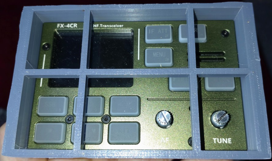
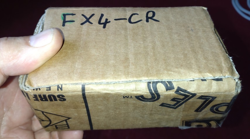
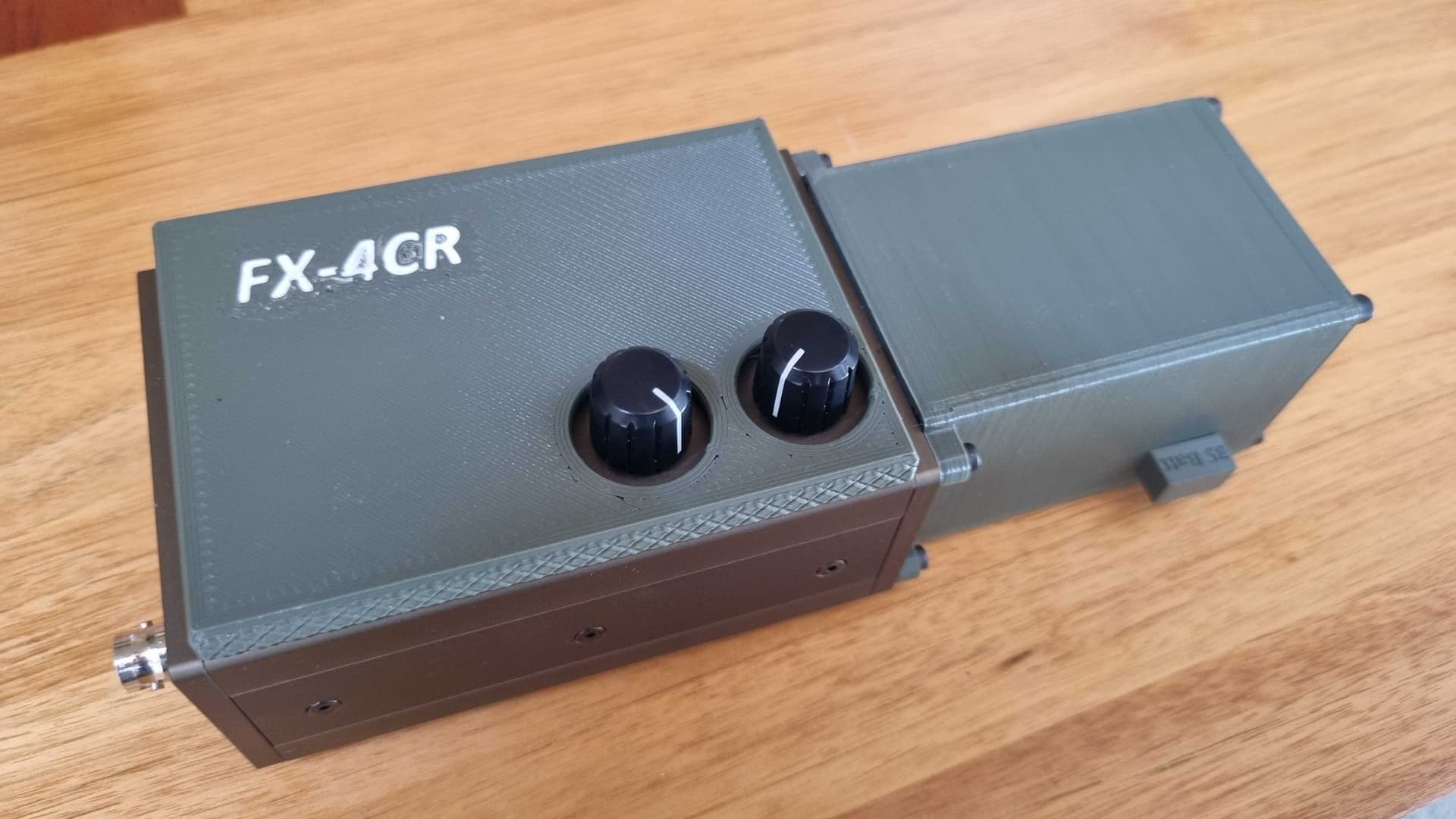
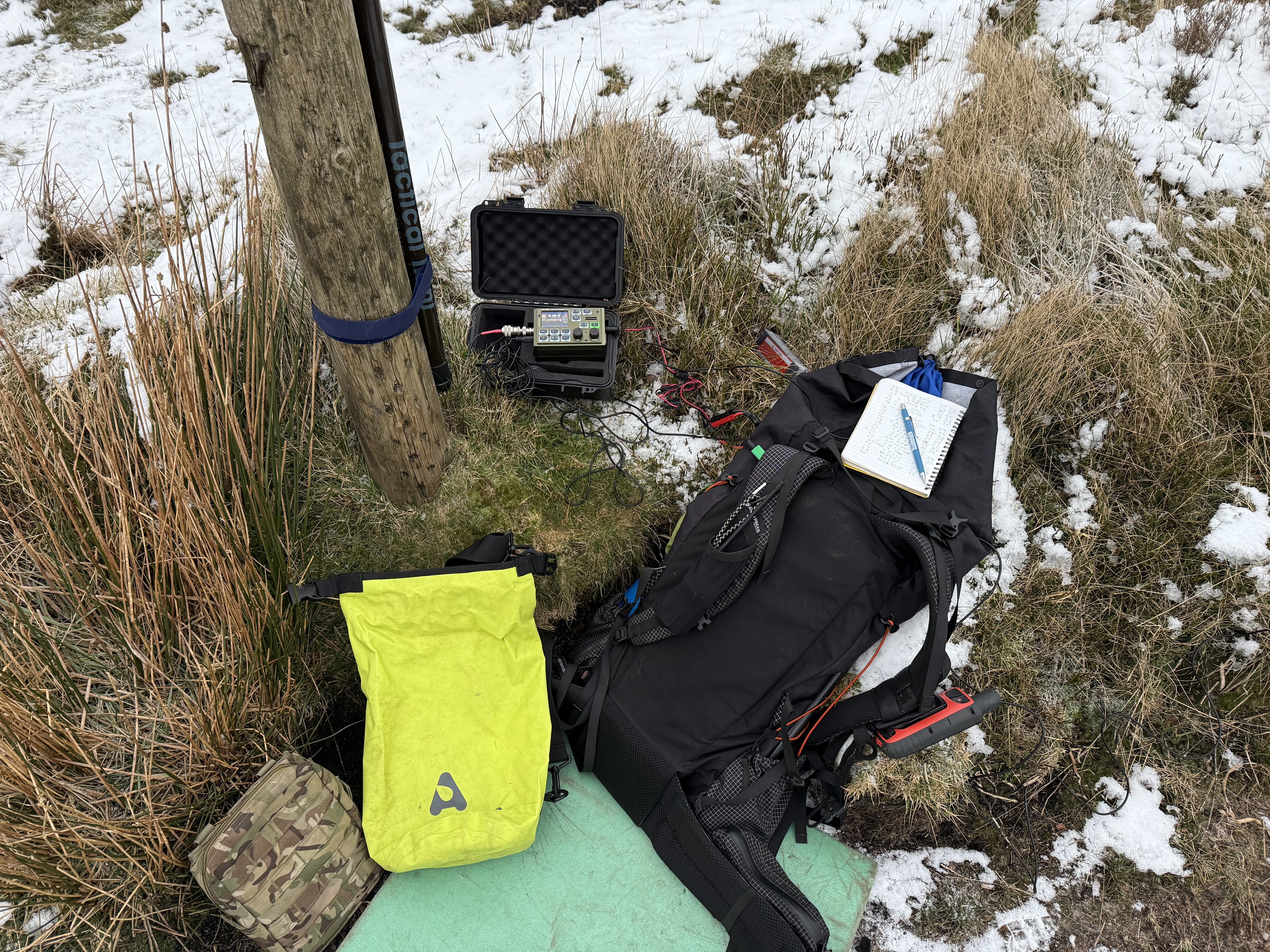
I have been using my FX-4CR (third version), bought in november 2024, and I must say it’s working pretty well.
Using the rig is easy and the most useful features (CW speed, power, tuning…) are accessible with the controls without requiring going into menus.

As explained before, CW mode was working just perfect, but when in SSB I had a few coments of bad or extrange audio when in higher bands (21 - 28 MHz).

It seems the rig is somewhat sensitive to RF feedback when using End Fed Half wave antennas and you are close to the antenna in the field.

To solve the issue I did two actions:

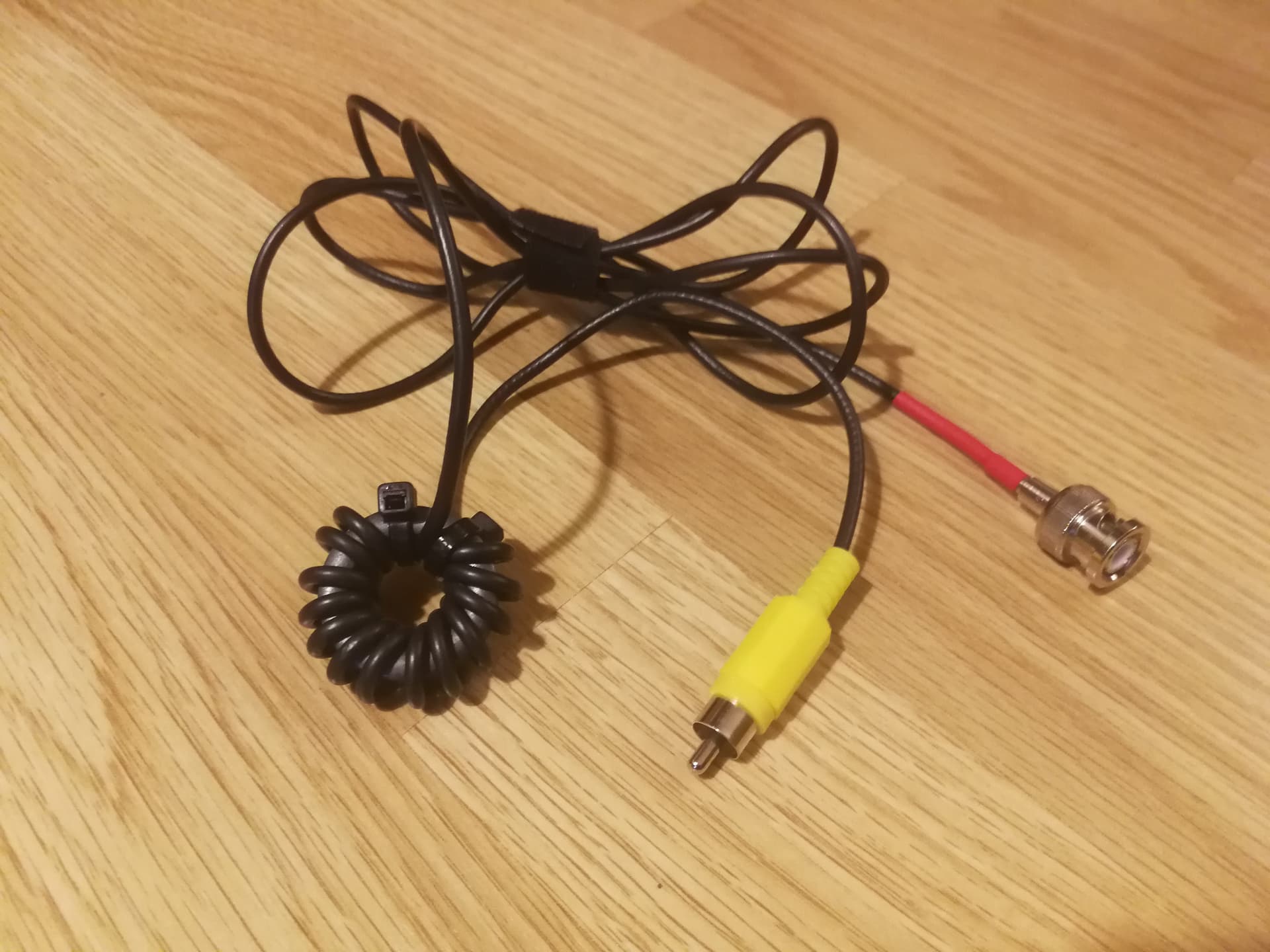
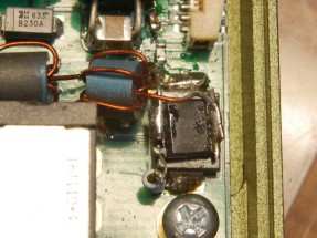
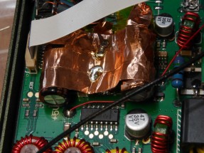
  1. I prepared a 2 meter long RG-174 coaxial and added a choke (14 turns on a FT 114-43 ferrite) near the feed point of the EFHW transformer.

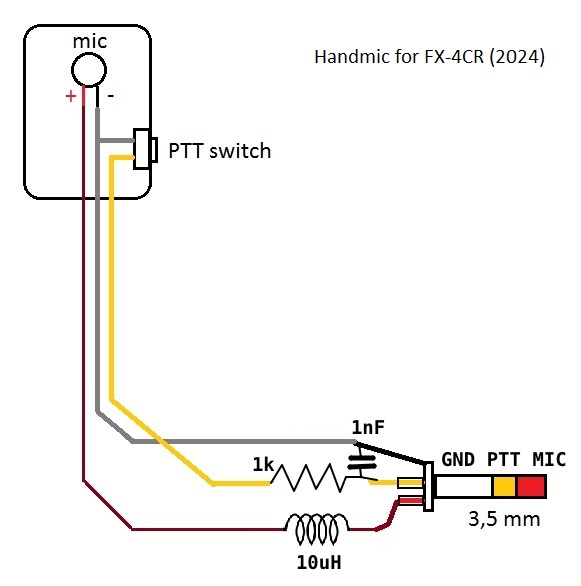
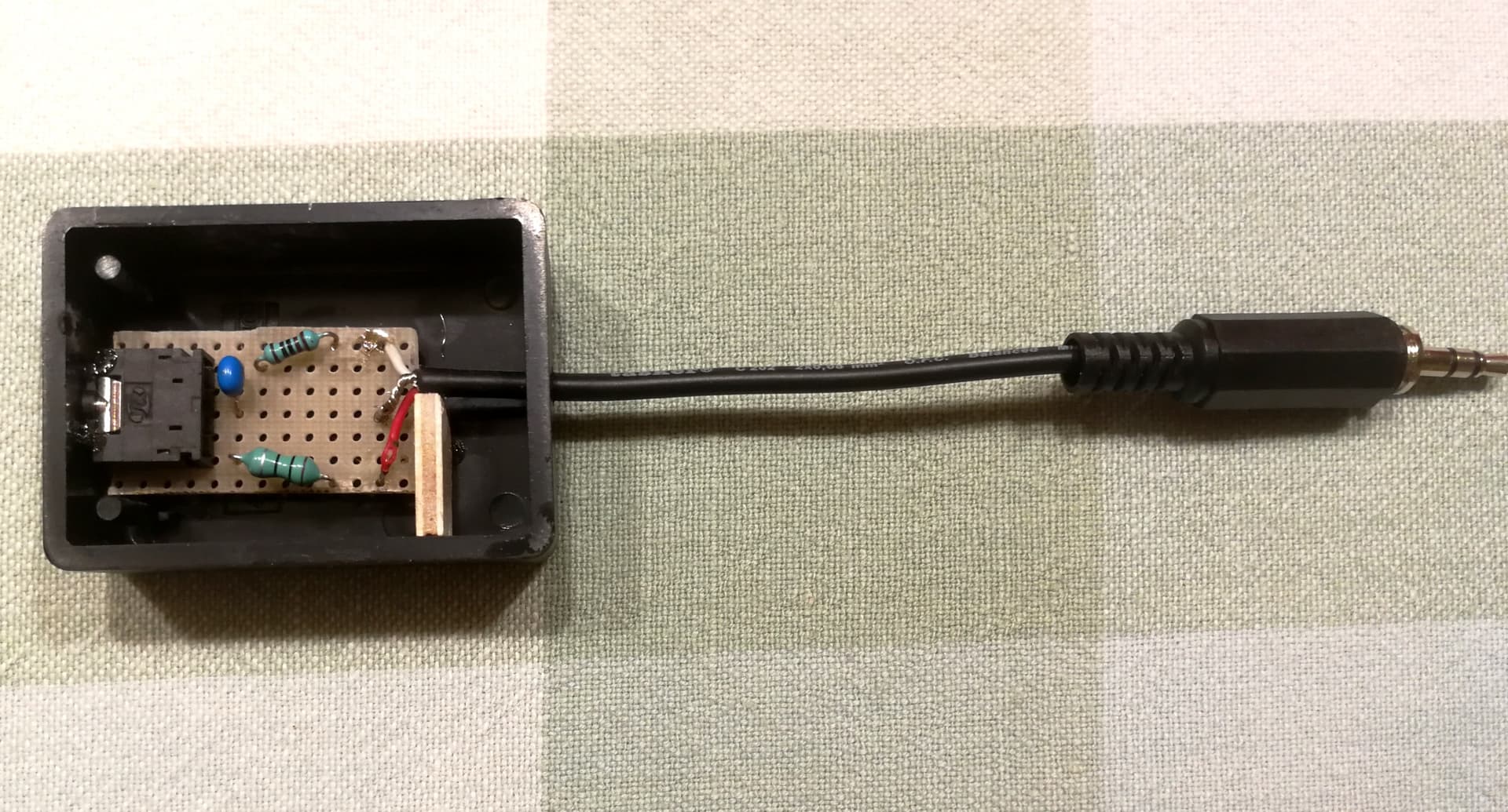
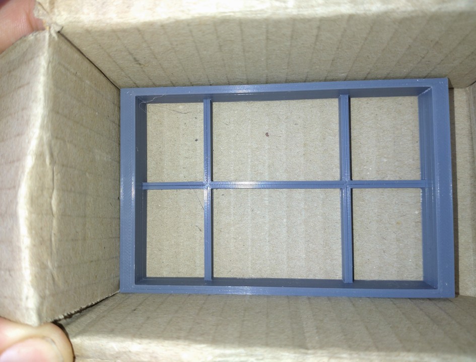
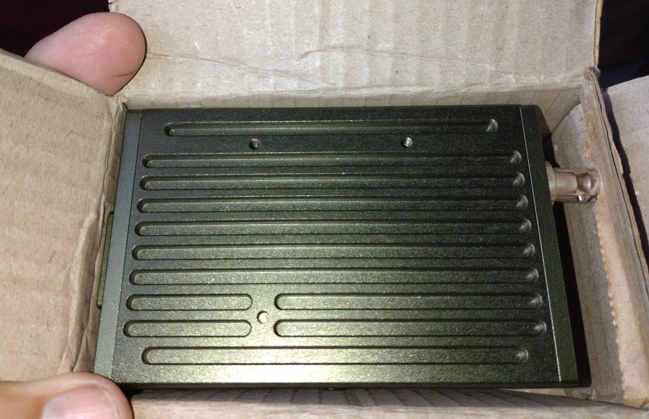
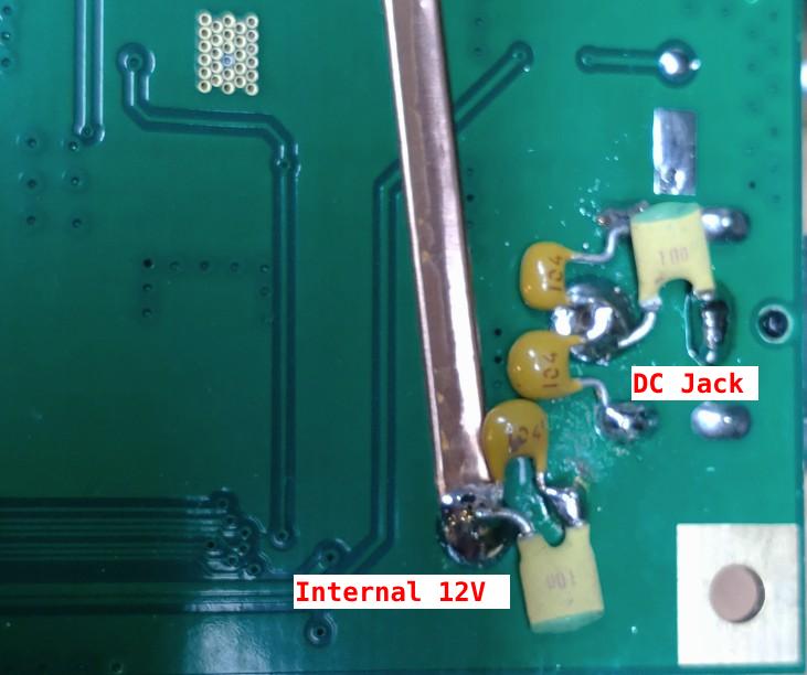
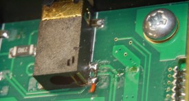
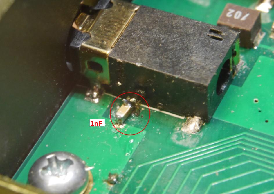
  1. I exchanged email with Simon ZL1THH who suggested modifying my hombrew small microphone to prevent from RF ingress via the mic cable. This is what I have now:

I tested on my last activation (2-Jan-2024) both in 28 and 14 MHz, and I asked several times to my chasers a feedback of my voice. They all replied my voice sounded right and nothing extrange.

It seems everything will be fine from now on concerning RF feedback.

Are there high power peaks on SSB transmission?

When I used the rig I observed that while I had settled my power lower than 10 watt, the display was showing some peaks of power higher than 10 watt at times, as I talked on the mic.

I verified I had correct settings on the rig, not producing the trouble due to an incorrect excessive gain. This is what I had in the menus:

  • firmware version: 1.7
  • mic gain: 10 (max 99)
  • TX Filter: 5 (0 to 5). 5 means 3 kHz bandwidth.
  • TX AF-Compress: 15 (1 to 99)

The instruction manual says that Mic gain should be not further than 10 to avoid distortion.
Okay, so the settings seem correct but, why are there these peaks?

At home I put a dummy load and to my surprise there were high peaks as well, so this is not related to the antenna in the field, but should be something in the programming of the rig for SSB.

I recorded a video that shows the difference between CW (acqurate power) and SSB (peaks at times), having settled the power to 10 watt. Pay attention to the display and measuring needle in the external meter:

As you see, by looking at the rig display and at the power measuring needle, the behaviour is very different:

  • CW: a key down produces a straight impulse so that the needle reaches the settled power straight on, while

  • SSB: the red bar on the rig`s display shows at times that the power is higher than settled (> 10 w).

Is that difference dangerous for the rig on SSB? The needle shows a very short jump coincident to the higher readings on the display, nevertheless, the power is not really going as high as for CW, so I suspect that the SSB peaks last a very short time, and probably not noticeable on air, maybe?

I had played the video very slowly and I see the peaks are produced here and there depending on the letter I spell, but they last miliseconds.

What do you think?

I’ll report YU, BG2FX, about this subject to see if there is any bug in the current firmware v.1.7

73 Ignacio

3 Likes

I have noticed that the ALC attack rate appears too slow, and I get 20W peaks regardless of set TX power.

I’m not sure if there is actually any speech processing, as I don’t see any change in the DC current drain when changing the TX AF COMP menu setting.

Also the small ALC display bar doesn’t really seem to relate to anything much, as I vary the mic gain it always seems to be in about the same place.

It would be good if you tell Yu that filtering works. I have made this point to him, but he was pursuing shielded mic cables and seemed to resist hearing it.

2 Likes

I use my FX-4CR since September 2023. 90% of my activations were done with it ever since. I operated exclusively SSB with an 12m long EFHW is InvVee. I’m quite happy with it. Haven’t done any firmware updates yet, which I probably should do :wink:
73 Alex, DK1ZX

1 Like

I find a separate battery quite annoying too. It’s a bugger of a design to make a small, neat battery for. Mine has a fan where your battery is!

I protect mine as usual with a cardboard box. I made a quick 3D print to stop the knobs taking any force as those little encoders just have fairly weak tact switches inside them.


2 Likes

Hi Simon, indeed, I wrote him to tell about the filtering and those power peaks. He said he made a note for it. Maybe the future will bring anything to solve it.

Hi Alex , thanks for the feedback.
I see you’re using a previous hardware version (v.2), and I’m not sure if you will also see those power peaks in the display: let us know if you do!
If you’re not sure just check the Pwr bar in the display while talking.

Quite a simple but clever idea Simon!

Just to be clear I finf the FX-4CR useable and valid for regular use as is.
The homebrew mic implementation I shown adds some filtering and protection.
The power peaks would be better if removed for a better life of the rig…

73 Ignacio

1 Like

That protection looks good.
I had a mishap where I arrived on the summit of Mt. Wills to find that the FX-4CR battery was almost flat. While bouncing around in the pack, something had turned it on (despite it being wrapped in a beany). To make matters worse, by the feel of the case temperature it had been transmitting too (the RIT button was configured for PTT with the attached battery).
There is a nice FX-4CR cover on Thingiverse, so I printed it and it does the job and provides partial protection for those knobs.

Since my last post on this thread, the FX-4CR has had a lot of use in Australia and overseas with great results. I’ve had the odd occasion where it had to be power cycled (V1.7 FW) after a lock up, but overall it’s worked well.
During the 10m challenge I noticed what sounds like processor or switch mode PSU noise that became apparent on very quiet summits when the volume was cranked right up.

Cheers Glenn VK3YY.

1 Like

I’ve done about 20 activations with mine now. I too was having problems with RF getting back into the radio, particularly on the higher bands. CM choke as suggested by some of my GM chums eliminated that. I’m also using a K6ARK microphone with a high quality screened lead. I worked into LU on an activation yesterday (SSB) and no more complaints about my audio even from strong, local stations. now.

Rightly or wrongly, I carry the radio in the padded, plastic case it arrived in with mic and power lead inside too. Plastic box and separate battery then go inside a waterproof bag. It might be heavier than some but it works for me.

3 Likes

Although it doesn’t support it yet, the QMX is supposed to have SSB soon with a FW update that is forthcoming. I have one and it is an exceptional radio and fun to build. The value you get for the price is probably second to none, expecially if you build it yourself. If you do build it yourself, I would highly consider getting a high band kit and then reading @AI6XG 's blog post on how to substitute 40m for 11m by acquiring a few capacitors and a couple toroids. That will give you 40m-10m but without 30m. I’m told now that you might even be able to include 30m with this build due to a recent FW update, but potentially at lower than advertised power since thrying to optimaize filters accross multiple bands will require compromise. Teh one downside to this radio, and it was a problem for me, was a bad PCM1804 chip that caused high noise on all bands triggering AGC such that the SNR of a received signal was extremely low. A replacement chip is only like $4-$6 from TI, but it seems like this has been an issue for a bunch of people and is unrelated to anything to do with the building process. In the end, you can have a radio about the same size as an MTR3B, but slightly heavier, with multimode and multiband capability and an exceptional receiver for something like under $150 all in. Great option to be able to throw in a backpack as a backup option.

1 Like

It is S3+ every ~200kHz from 3MHz up. Falls close to 21.310 for me and drifts through it.
Quite a bit leaks out the power jack, so I have put beads inside to filter that, but it does leave the internal leakage. Yu’s SMPS pcb layout is poor, and there is no secondary filtering of the 5V rail. It is actually much less interference than might be reasonably expected. Unfortunately the pcb layout doesn’t give any obvious place to insert extra filtering of the 5V. I have just got some more chip caps, so will see if I can reduce it.
The smps chip he uses does have a frequency control input, so it is possible to move the spurs around, but I can’t see a “move spurs” switch being a desirable mod.

From time to time, the whole band 12m or 10m will be filled with broadband noise (not 200kHz harmonics). It seems to come in the antenna, and I have filtered my DC jack. I don’t really know if it is anything to do with the radio or totally external.

The buttons are very light. Years ago I had an OM4 camera, and if you oriented it wrong in your pack, the shock of footfall was enough to semi-press the shutter and wake the meter up, repeatedly, flattening the battery after a week or so. Took quite a while to work out what was happening as nothing touched the button, and normal battery life was years.

They draw ~3W on RX, so if you had it wrapped in a beanie it might have been nice and warm without any TX.
Also off current 0.85mA - enough to flatten batteries in a few months if you just stuck it on the shelf and forgot about it.
If your bms uses S-8254 chip, then you can have a low current switch to turn the battery off

Same here, every now and then it gets into a strange mode that turning it off fixes. Not enough to be annoying. I am looking forward to Daniels F/W for my version sometime.

I am also looking forward to it, though I wouldn’t be holding my breath for it to be “just a firmware update” with the early circuit design I looked at. I am waiting for the SSB to hit rev 2, before I buy the expected revised kit.

Unfortunately despite his radios popping BS170s like Freddy Mercury at a backstage orgy, Hans seems determined to persist with unsurprisingly delicate final transistors.
And what is with expecting the customers to source replacements themselves for counterfeit or used PCM1804s in his supply chain?

4 Likes

this is not an inaccurate assessment, but I will say replacing the BS170s is fairly easy to do and I have a whole bag of them for this purpose. And you may be right regarding the SSB functionality, if and when it arrives. For me this was not super material in my purchase since I usually only do CW, yet it would be nice if a mere FW update would add more functionality. If not, perhaps I get to build another kit!

1 Like

I don’t see that on my FX-4CR. It’s the first version hardware and using V1.7 firmware. With no antenna, I can hear a slight increase in noise every 80kHz, but it doesn’t move the S meter. The low level processor or SMPS noise doesn’t move the S meter, but it’s noticeable under very quiet conditions on the higher bands.
BTW, what happens if you cycle through the filters several times while listening to a signal? Any change in signal amplitude?

Cheers, Glenn VK3YY.

1 Like

Inside it again, adding a little SO-8 reverse protect pfet in series with the +12V
Beads_ReverseProtectFET_AO4447_P1230010
You can see the beads to filter the SMPS 12V side noise.

And bypassed the headphone jack so that the speaker still works when the earphones are in, as that’s how I like it.
HeadphoneSocket_Speaker_always_on_P1220989

And put a 1nF cap across the PTT pin of the mic socket, as the factory mic goes spastic on 12m with EFHW.

I’m not sure where I got ~200kHz from, the SMPS is at ~560kHz, it has a 180k resistor to set it, so that is about as expected from the datasheet.
I have put beads between the SMPS and +12V, so the leakage via VCC and the power lead has gone, and the level is down since I did that.

This produces a squeeging noise (on AM) that is about 7kHz wide, which drifts through 21.310 (14.019,15.136,15.697,26.905,28.025 … i.e 560kHz harmonics)
Using 50hm terminator on the BNC, AM, 9kHz BW, it is at -107dBm at 21.310 and generally in the -105 to -110 range.

I have added various chip caps to the 5V now without reducing the noise much. The noise isn’t going through the 5V rail.

Some shielding foil over the smps inductor reduced it to -115dBm, but more foil increased it.
Foil_over_smps_P1230011

Opening and closing the case halves and touching wires doesn’t change it much.
But when I tighten up the BNC end plate, and especially the middle plate screw closest to the BNC, the noise rises to -100dBm or more.

So it looks like an earthloop from the smps input side noise through the BNC area to the middle plate holding the RX. Yu doesn’t appear to use the LPF’s for the RX

The same happens if I have the case open, and use foil to join the BNC shield to the centre plate.

3 Likes

I have loaded Daniels V2.02 firmware, and the 20W peaks have gone. The ALC doesn’t exactly hard limit to (say) 10W, but it is not problematic.
The slow start at Po>10W issue seems to be gone also.
It can do out-of-band TX now.

Got a good audio report today.
Mic gain is low - too low to use internal microphone, but does work on my external mic.

I noticed on 10m that I can hear some rf in the headphones. Looks like it needs filtering on the headphone lead too!

2 Likes