I agree that #31 or #43 ferrite is a better material than #2 powdered iron for a balun core.
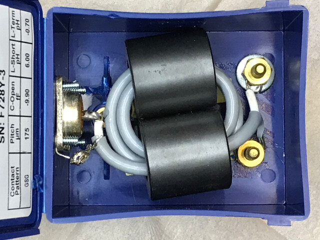
One of my QRP baluns is made using a two side-by-side “ferrite suppression sleeves” designed to slip over cables, with the cable looped through the pair of them - a smaller version of this:
The common cores about 25mm (1 inch) long and 13mm (1/2 inch) in diameter with a 6mm (1/4 inch) bore should take 4 turns of RG-174 with a bit of work (or 3.5 turns if you want the cable to come out on opposite ends). That should work at 20m and higher frequencies: I switched to RG-178 (the next size smaller than RG-174) to squeeze in an extra turn for better performance on 40m. But the cores come in many different sizes, and a larger core size makes it easier to wind.
In my case, even at QRP power levels, my keyer would continue to send when I released the paddles when I had common mode current. The effect was worst when I had a longer piece of coax between the antenna (1/2 wave end fed through an L network ATU) and the radio. In that case, adding a radial wire to the ATU case reduced the problem.
With a quarter wave vertical, the radials should reduce the impedance at the feedpoint enough that “RF in the shack” isn’t as much of a problem with a short cable, although it certainly can be when the feedline is close to 1/4 wavelength. In that case, changing the length of the coax, adding a quarter wave radial wire connected to the radio chassis, or grounding the chassis somehow (often not very practical on a summit), may reduce the problem.
You do not specify the ground radial system in use. Without it you do not have a complete antenna and can expect the RF that should be on the radials to flow on the outside of the feed line.
The ends of quarter wave radials are a high voltage point, make sure they are insulated off the ground. If you ground them, they are no longer resonant and do not provide the right radial effect. A grounded far end means a high impedance at the feedpoint, almost no current will flow in the radials and the outer of the feed line will be the only place current can flow.
Also they should be symmetrical to be sure there is no net radiation from the radials, they should be equal and opposite, three radials should be positioned at 120 degrees from the feedpoint, which will ensure their radiation cancels out. Once you have the ground system symmetrical you will no longer have current on the outside of your coax and you, your radio, battery and key won’t be part of the antenna.
Nice build. I looked at the various “loop a coax through a ferrite” or “just loop coax in the air” approaches. The “ugly balun” (air wound coax inductor) actually did the job, but I haven’t got enough coax with me to make it work.
Adding radial wires/ground wires to every component in the system sounds like a great idea, thanks!
Actually, the worst CMC problems happened using a 6m+ feedline (at 20 meters). But even a 2m feedline is having trouble.
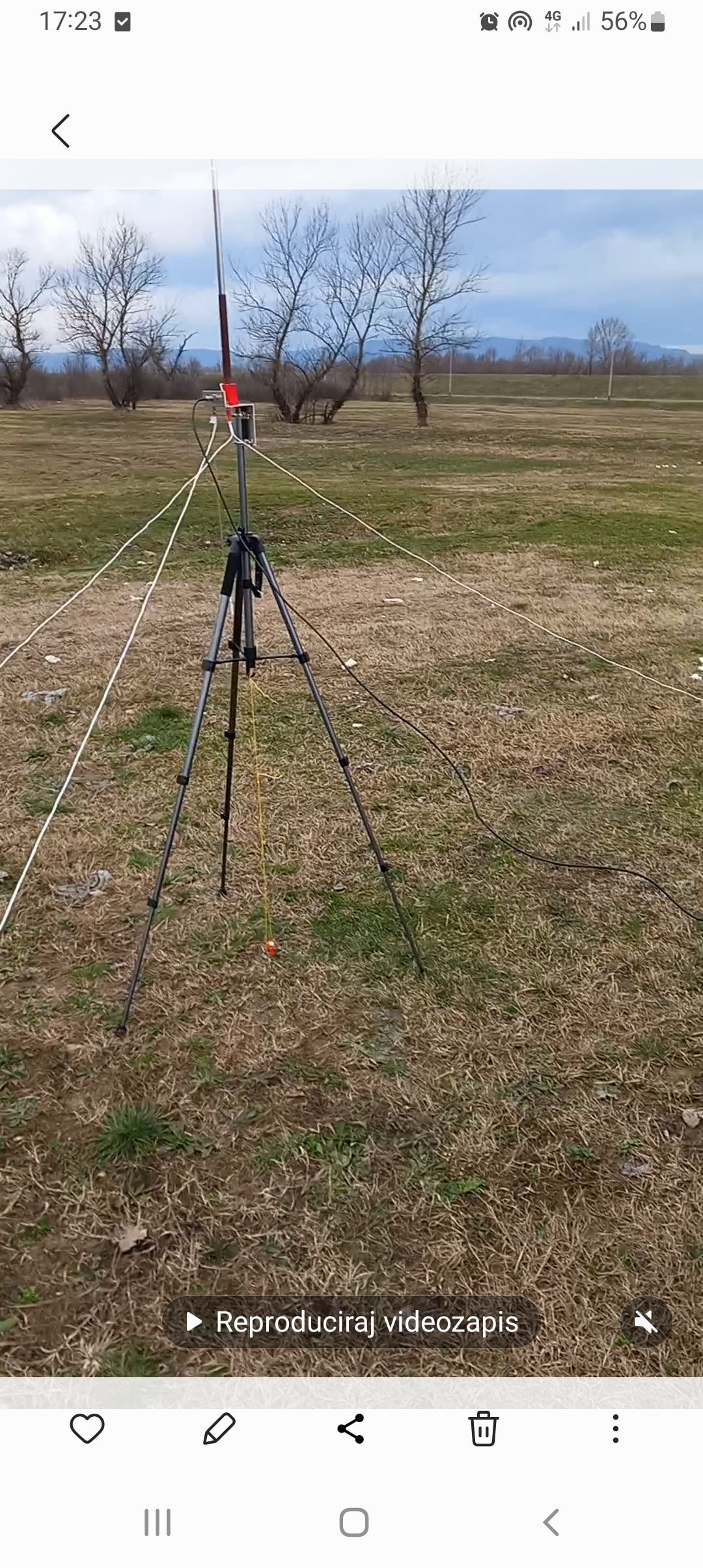
I am a bit confused about radials. Right now I have a single 1/4 wave length radial. I will try again with multiple radials, following the discussion here.
I thought that the purpose of the radial was to provide capacitative coupling to the ground, and create the ‘reflected antenna’ or ‘virtual dipole’ effect that we learned when I got my license.
Now people are saying the radials are very much acting as antennas also…?
Currently the ground radial system is a single 1/4 wavelength radial.
Elevating the end off the ground did not make much difference.
I will try making symmetrical radials and see if that helps, thanks!
Still, having to make the radials 1/4 wave and insulated off the ground is strange. Shouldn’t it also be possible to ground the antenna well (e.g setting it up over salt water) and have it perform very well? Aren’t the radials just acting as a “virtual ground”?
When you said 1/4 wave vertical, most people will be thinking 1/4wave GP. What you have is not one of those!
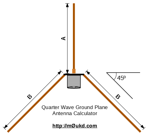
I’ve used 2x 1/4wave GP antennas portable for 12m and 10m. They consist of a vertical 1/4wave radiator and 3x 1/4 wave radials sloping down from the feed point at 45degrees. The ends of the radials were insulated from the ground. The elevated feed point was fed with 4m RG58. I was sat with mainly an FT817 at the time right up close to the antenna with no issues. Those antennas worked brilliantly and were DX magnets. So I would fix the radial situation first.
For a CMC choke on my dipoles, I have 6 turns of the feeder solenoid wound into a coil 125mm diameter with input and output on opposite sides. The coax is RG174 and the coil is mounted at the junction of the coax to the dipole legs. No RF feedback.
On a 20/30/40m trapped EFHW I use a 1:49 match and a 2-4m long counterpoise. 4m RG58 feeder. Again no RF feedback. There is a clip-on ferrite with 3 turns of RG58 through it at the radio end. It was added because I found the clip-on in a junk box. It was never needed before but was added as it cannot do any harm
Right, okay. I’ve never heard of an L-shaped dipole but I can see what you mean. I will try adding a second (opposing) 1/4 wavelength radial and see if that fixes the CMC issues.
There are a lot of different factors involved. For example, elevated radials work differently than radials on the ground. But, yes, radials ARE part of the antenna, have RF current on them, and will radiate (unless the radials are arranged to cancel that radiation).
I address some of the issues in this study:
There certainly is a lot of confusion and misunderstanding about radials / counterpoises / earth/ground systems (even on some license exams). Elevated radials are an active part of the antenna, and sloping radials will radiate vertically polarized radiation (but, if symmetric, the horizontally polarized radiation from them will cancel). That’s why tilting the radials downwards raises the radiation resistance. Tilt them all the way down and it looks like a dipole: it is often easier to understand if you think of it as a vertical dipole with the bottom wire split into several parallel strands and the ends spread out.
When wires are laying on the ground, they are detuned by the dielectric constant of the earth, so they are no longer resonant (at least not where one might expect based on the length: often they end up resonant around half the expected frequency, depending on the ground spacing). In that case, using enough of them to form a capacitor to ground isn’t a bad understanding.
The basic point is that at the feedpoint, whatever RF current flows into the “radiator”, must also flow into the “ground system” connected to the other side of the feedpoint. The lower the impedance of whatever is connected to the coax shield, the less current flows back down the shield towards the transmitter. (The impedance looking back down the outside of the coax is also a factor: a balun/choke increases that to reduce the common mode current.)
One or more resonant quarter wave wires connected to the coax shield will have a low impedance at RF. If they aren’t resonant (due to laying on the ground, perhaps), then the alternative is to provide a low impedance some other way - like a large non-resonant mass (the Earth). In that case, the exact length of the radials isn’t as important as providing low-reactance coupling (large capacitor) with a low RF resistance (spreading the current over a wide area).
So, yes, it is complicated, especially because physical the same antenna at different heights above ground will operate differently, require different methods for optimization.
That’s a common misconception. Elevated radials radiate, rather than reflecting. Ground reflects (or absorbs), rather than radiating. An elevated ground plane antenna will have a vertical radiation pattern that depends on the height above ground, just like a dipole or other vertically polarized antenna, due to ground reflections.
Salt water is great for vertical antennas! But you still need the whole antenna: either resonant radials, or a good low-impedance connection to the salt water if you want to use that instead. (That isn’t always as easy as it sounds, especially with corrosion over time. And any wire connecting the feedpoint to the water acts as part of the radiator.)
I had one of the cute little portable vertical antenna kits (expensive!) with an adjustable loading coil where the instructions said it only needed one quarter wave radial per band, and that could be wadded up and stuffed into a backpack for use while walking. I was testing it for a friend because he couldn’t get it to work. I set up on a table outside with one radial each for 40m and 20m laying on the ground, and couldn’t get it to tune up either. Then I laid it over some plastic garden pots and it got better. Finally I hung the end over a wood fence so it was clear of the ground for the full length, and it worked as designed. (I suspect the elevated radial wire might have radiated more power than the short “radiator” attached to the loading coil, but at least it would tune up to a low SWR.)
So there really are two distinct pieces:
The radials, or whatever else is connected to the coax shield at the feedpoint, where the “other half” of the RF current goes.
The ground (or sea water) underneath the antenna. The conductivity of the ground, and the height of the antenna above the ground, affect the vertical radiation pattern of the antenna.
In practice, a single vertical wire with one quarter wave radial will work, but best if the feedpoint and the radial wire are elevated above ground, That way the radial is resonant, providing a lower impedance for the ground current, so less of it flows on the outside of the coax. Two radials running in opposite directions (or whatever you can manage) are better. Elevating the radial even as much as 30cm off the ground can make a big difference in efficiency, among other things.
I normally carry a dipole kit, with a pair of wires for each band that I attach as needed. When I’m going to be around salt water (uncommon on summits, of course, but I do have to visit family in KH6 on occasion) then I add a third wire for each band to use as a hanging vertical, with the two dipole wires as the radials. Yes, nominally they would all be the same length, but that isn’t always the case due to ground effect. The two radials slope downwards from the feedpoint, which hangs from the vertical wire. I could just hang the original dipole sloping down from the same support, and it probably would work about the same. (Or I might use a vertical loop instead.)
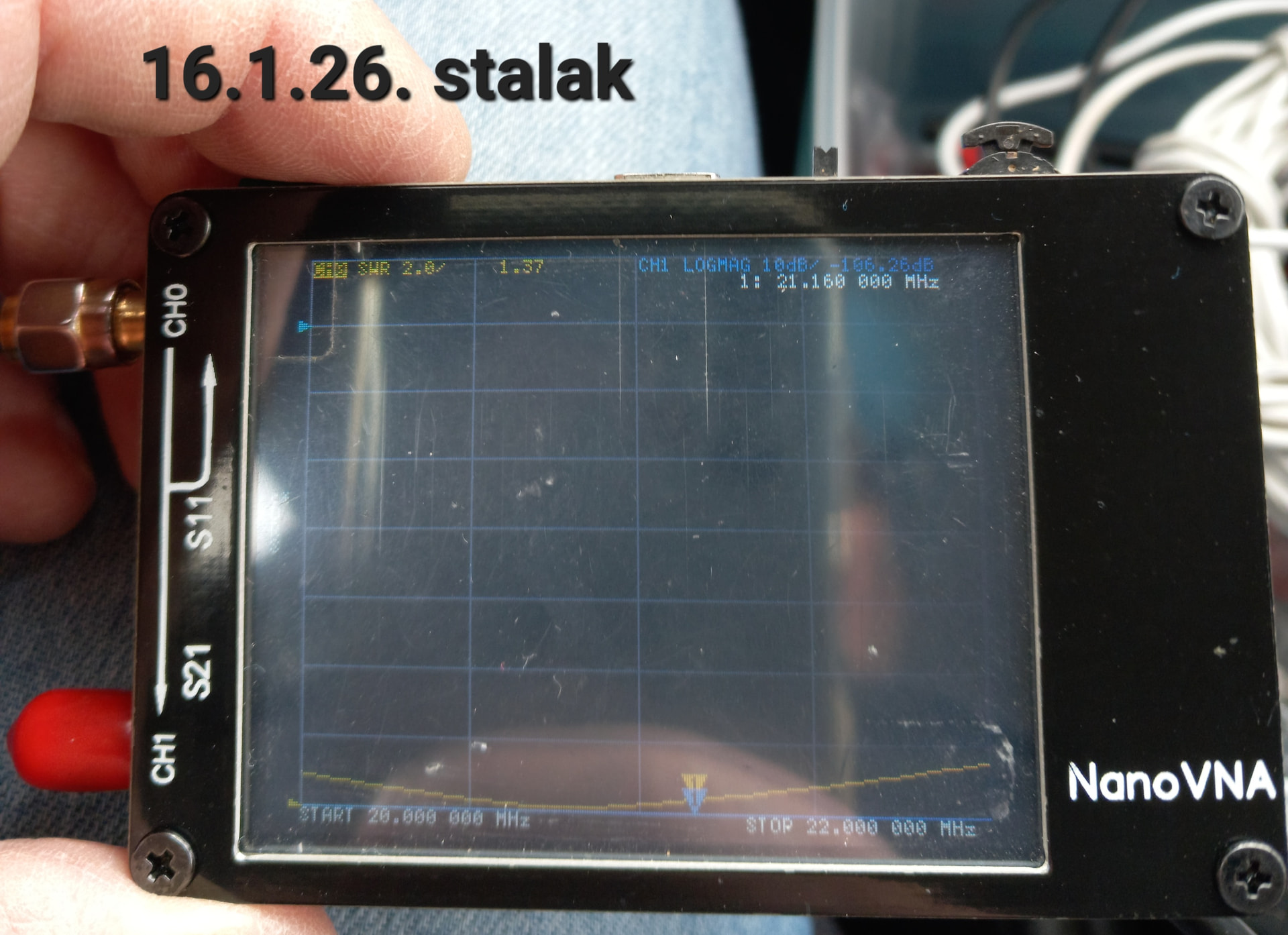
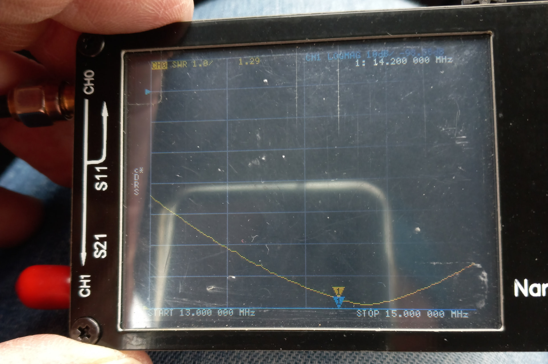
I tried adding an elevated 2nd 1/4 wave radial at 180 degrees to the first one. It made things worse (!), instead of SWR 1.2 the 2nd radial raised the SWR to 3.5.
Tried adding a 3rd radial and that dropped the SWR to about 2.4.
Putting all radials on the ground, instead of elevated about 50cm (the feed point is approx 50cm off the ground), helped a little. But not much.
Attaching a radial to the transceiver made things worse.
Touching the transceiver (which has an aluminum case) changed the SWR noticeably.
That wont work with 1/4wave elements because they need to slope down at 45degs for a 50ohm impedance. As in the picture from M0UKD’s webpage.
If this is for 20m then that suggests a feed point about 3.5m above ground. You don’t need 45 degrees but if you change the angle, the feed impedance changes and you need to alter the lengths to get back to 50ohms.
No, that probably won’t help. If the current antenna is resonant, than shortening the radials will only make it worse.
The antenna impedance has two components: resistance and reactance. For a low SWR, you need both 50 ohms resistance and 0 ohms reactance (or something close to that). Changing the antenna length changes reactance faster than resistance. (When the reactance = 0 ohms, we call the antenna resonant, but that doesn’t mean that the SWR is necessarily low if the resistance isn’t close to 50 ohms.)
With the base of the antenna 5m in the air, horizontal radials will give a feedpoint impedance of about 22 ohms, so the SWR is > 2 : 1, even when the antenna is resonant. At 50cm above the ground, it might be closer to 32 ohms (due to ground losses), for an SWR of 1.5 : 1, but only if the radials are elevated, so they are not detuned by the presence of the ground.
When the radials are laying on the ground, it is much more difficult to determine, because it will vary more with the ground characteristics, the presence of grass, moss, or heather that space the wire up off the ground, where along the radial it touches the ground, etc. All that changes the tuning of the antenna - and you likely won’t end up with the same conditions each time you set it up.
With the feedpoint at 50cm, the ends of the radials can be tied off with pieces of rope to whatever supports are available (or even a tent peg, to keep them off the ground. Yes, that takes more setup time than just tossing a wire on the ground, but it provides a more repeatable match, as well as higher efficiency (more radiated power). And when the radials are resonant (not just the wire length, but free from the detuning effect of the ground) then you should have less problem with common mode current.
In fact, common mode current can make it much more difficult to tune the antenna properly, because any minor change, like touching the transmitter case, coiling the feedine differently, or plugging in the headphones, can change the SWR. I have spent some very frustrating hours trying to tune antennas (lowering it, making adjustments, raising it back up) where the SWR would change after each cycle even if we did not make any adjustments to the antenna.