Some time ago I looked into this question of whether 50Ω and 75Ω BNC connectors are sufficiently compatible to mate with each other without damage. I concluded that they are, or at least are supposed to be. I see no reason to change my mind. The Wikipedia article asserts that they are “dimensionally slightly different”, but it cites no references and gives no actual figures. I think it is a myth.
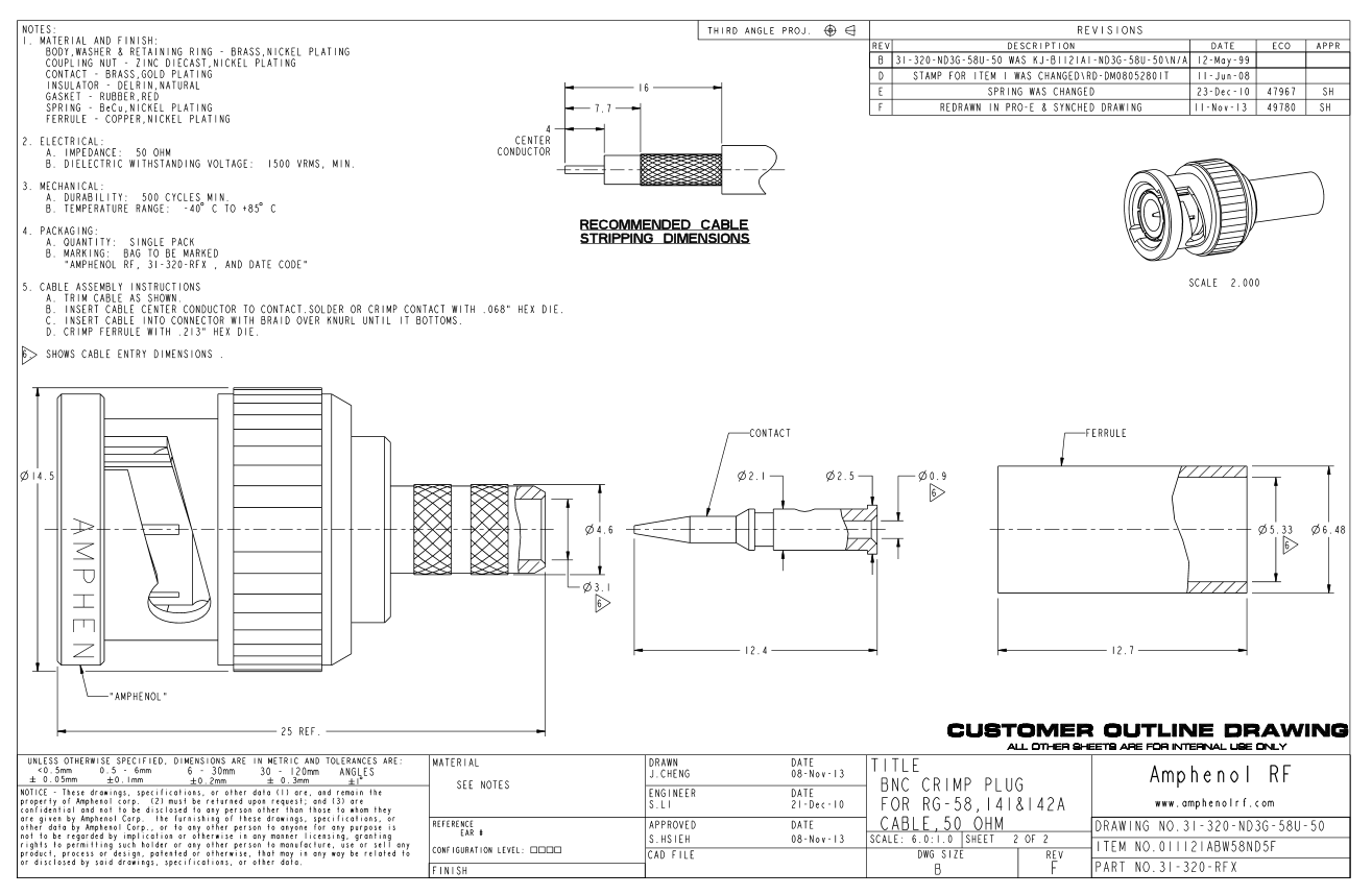
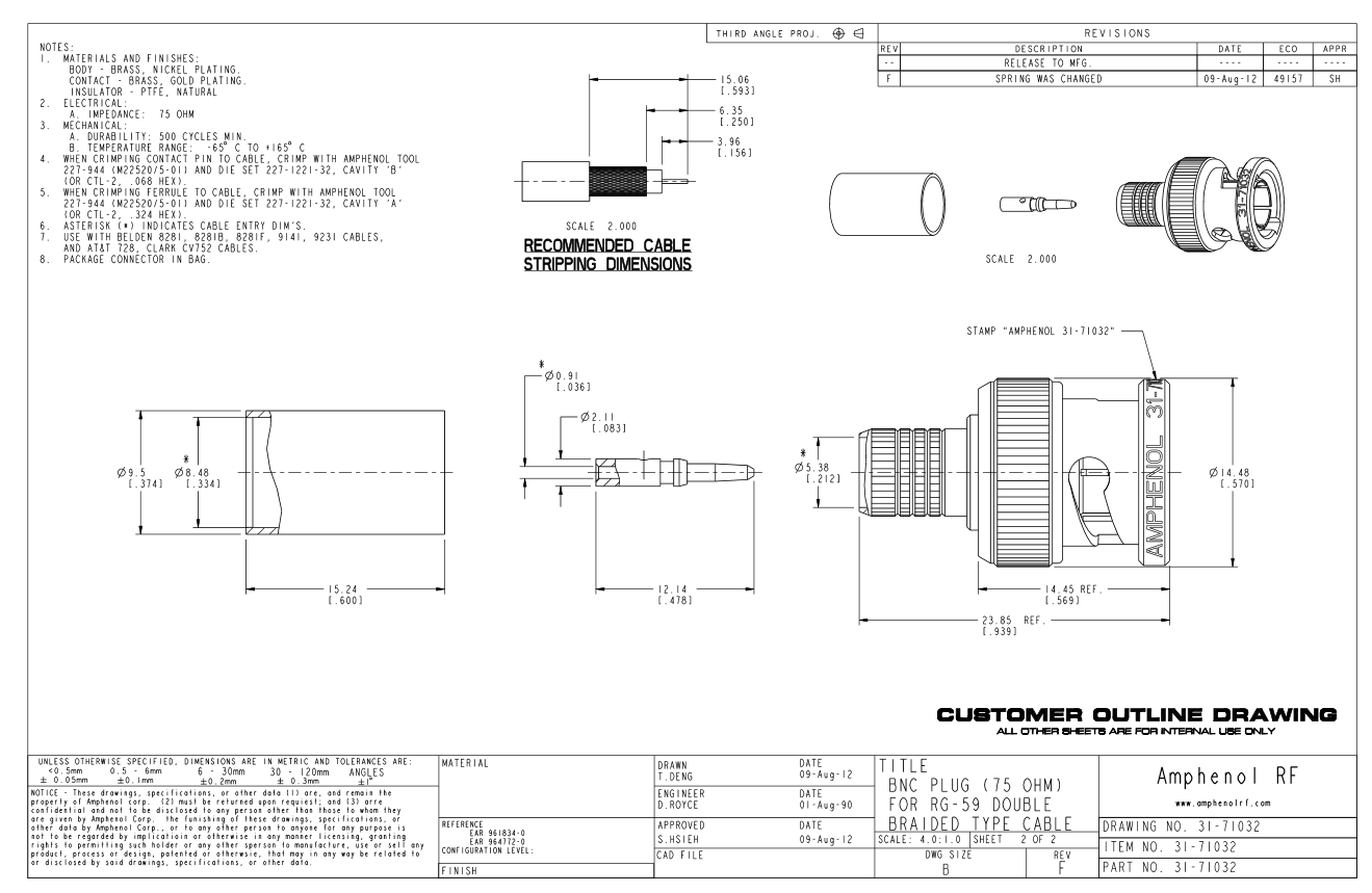
If you search for the mating interface specification, you can find any number of dimensioned engineering drawings giving the diameter and relative positions of the mating surfaces. None of these drawings specifies the impedance, or comes in two variants. As far as I can make out, there is just one interface specification.
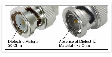
Of course the 50Ω and 75Ω connectors are different. Most notably they have different arrangements of the dielectric. There may also be differences in the metalwork in places other than the mating surface. Both of these are likely to give the visual impression that the pin diameter is different, when in fact it is not.
If you think about it, there is no need for the pin diameter to be different. What matters for impedance matching is the inner diameter of the outer conductor and the outer diameter of the inner conductor, both measured at the point at which they meet the dielectric medium which lies between them. The mating surface is a metal-to-metal contact and is not the interface with the dielectric. Its diameter is a matter of mechanical design and is irrelevant for impedance matching the transmission line.
There is a Farnell datasheet which asserts that it is actually impossible to make an exact 75Ω impedance match within the constraints of the BNC interface specification, but that the ones made are close enough in practice at the frequencies at which they are used.
My conclusion is that yes, we should always use the correct type for the job in hand, but we need not worry about interconnecting them. In particular if you actually want to exploit a mismatch as an impedance transformer, it is perfectly OK to connect the two kinds of BNC to each other.
Thank you Martyn. I was finding it difficult to locate drawings with pin diameters shown, but those I did (from TE) had the same values for 50 and 75 Ohms. Like you say, this isn’t a dimension that affects the impedance and most likely the dielectric is something else they will modify. Of course there’s a difference between assuring non-destructive mating and it actually being any good!
In my opinion assembly error (pin protruding too far, solder on the contact surface) is at least as important to look out for, although obviously you shouldn’t set out to mix the connectors.
Or should you?..
Say I wanted to carry a quarter-wave 75-Ohm extension for use on-summit as a transformer to ~100 Ohms. Should I terminate in the correct 75-Ohm connectors, reducing the risk of major confusion at a later date, or try to fit 50-Ohm connectors to be sure of a good mate? It would certainly be wise to check it thoroughly before counting on it.
My biggest problem with BNCs has been the blighters dropping off! I would still like to find a reasonable source of good ones like I used years ago (Greenpar I think, silver-plated) that had the top-hat style ferule you slipped under the braid. Everything I get from Farnell/RS nowadays has a sort of coned washer and it’s not nearly as effective.
They say:
“…The Impedance of the various devices being connected as well as the Coaxial Cable itself must match. Every single time you have a mismatch in impedance, say between a 50 Ohm Coaxial Cable and a 75 Ohm Coaxial Connector (i.e. BNC), a standing wave develops.
A standing wave is a signal reflection that is essentially wasted. Every time a 50 and 75 Ohm Impedance mismatch occurs, about 5% of the signal is lost. These losses add up and can eventually degrade the signal to the point that it is unrecoverable or distorted. Some coaxial cable manufacturers will cut corners in this regard. …[BNC] It is extremely popular, but most people don’t realize that they come in two versions: 50 Ohm and 75 Ohm.”
They were the “mutz” and yes Greenpar was the manufacturer. You can get them from Westlake still, ISTR. I acquired a large box of them when there was a big cleanout of a lab where I worked some years ago.
As for which cables and plugs, you can look on a TDR and see which setup looks the least horrible! Though you need a better one than the one I made about 25 years ago. That could spot gross impedance changes and was accurate enough to find a break in coax to about 15cm.
When I first got my licence in early 1960, the standard antenna connector used in amateur radio equipment was the Belling Lee coaxial connector. It was even fitted as standard on most of the early commercially manufactured HF equipment of the day, for example the KW Vanguard, the Labgear LG300, the Panda PR-120V, etc.
I think that is what the article says. There are connectors and connectors and for HF (& 50MHz) and at lowish powers, there is little to chose on RF performance. When I first saw F connectors in the early 90s with the Sat TV boom, my immediate thought was “what a nasty cheap and tacky connector”. But the performance is really rather good.
The issue boils down to the inherent naffness in the fitment of the 259 and that for SOTA, a PL259 weighs more when every gramme counts. Brian insists that the BNC is poor based on his real-world experience of multiple BNC failures. SOTA activators are not reporting any where near the same level of failures which suggests something else wrong contributing to the failures Brian saw. The connectors were failing, but were they jumping or being pushed?
Well, bearing in mind that the unreliable BNCs that I experienced all came on leads obtained from the manufacturer of the ultrasonic test gear - one broke, you requested a replacement - I suppose that a plausible explanation might be poor quality.
Was it more often the head end that broke? Just wondering if mechanically coupled ultrasonics could have been a factor…? If it was a low power device, I guess not!