CM Choke on 49:1 transformer !?

I would suggest to make a two step process.

First measure just transformer + resistor and see losses in transformer only.

Then measure your CMC, which should be 50 ohm on input and output so you can connect it directly to nanoVNA.

Adding both results will give you total losses.

What’s more you can verify if both components are sufficiently efficient for your needs. At the end of the day one or the other might need some adjustment.

GL 73, Marek SP9TKW

1 Like

ok, i’ll take part in the guessing game :wink:

What Marek SP9TKW said seems to be a reasonable process. You shouldnt have so much loss. The 0.05lambda counterpoise is only needed for real operation, not for your measurement. Another remark: Your resistors are non reactive? You need to use resistors, without a complex part (inductive or capacitive).

Personally I had bad experiences with a metal housing for my Unun… so I would guess, that the toroids effect each other negatively. Try to seperate them, if possible, and repeat your measurement.

GL, Peter

Ok this is what I just did. With the same calibration I measured everything individually and together. I even added, in the comparative, another 49:1 that I made before (called “original” here). I used the calculator from Owen.

Exemple at 14 mHz:

S11 S21 Adjustment Insertion loss Efficiency %
49:1 + capacitor -43 -17,8 17,1 0,7 85
49:1 alone -13 -18,2 17,1 1,1 81
CMC alone -31 -0,16 0 0,16 97
49:1 + CMC -9,7 -23 17,1 5,9 28
49:1 + CMC + CP -32 -19,9 17,1 2,8 52
49:1 original + cap -30 -17,8 17,1 0,7 85
49:1 original -12,7 -17,9 17,1 0,8 88

I think it’s clear, insertion loss is acceptable when they are measured a part. When plugged together, catastrophy, efficiency drops massively (28%). It is a bit better with counterpoise (CP) (52%)

Saldy it seems like not. If I add 1.1 + 0.16 = 1.26 , far from the 5.9 measured !!!.

Yep, I separated everything for this test.

Interesting results. Maybe this is completely wrong, but I have the impression that the magnetic fields influence each other. How far apart were the two toroids during the measurement?

Both “flat” spaced with 1 - 2 cm. Same result when “on top” of each other.

Hi All,
The following was posted years ago, and is related; This also requires a counterpoise in actual use.
K6HPX

Nov '19

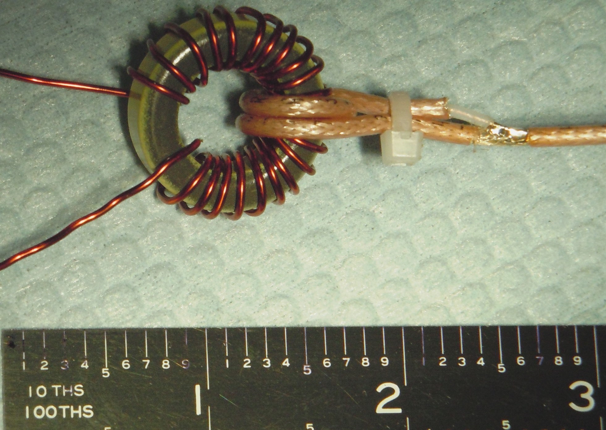
One thing to be considered, applicable to some of the simpler designs, is to use an N-turn Faraday shielded link instead of just N-turns. As many may know, this allows better isolation of the rig from the tuner / antenna, makes the antenna use the counterpoise instead of the rig, etc. see PIX: this is a 2-turn example, coax from the rig not connected to anything except by inductive coupling.

Best, Ken

2 Likes

I think what I’m trying to do is just impossible. I found this:

Since the coaxial shield is acting also as a counterpoise CMC should only be placed on the feed line if needed, & if you are using a EFHW antenna it needs to placed 0.05 of a wave length of the lowest band.

Source

It means the CMC should be 2.15 m from the transformer when your lowest band is 40 m. I guess I will put it right at the radio then.

Using the coaxial cable shield with 0.05 lambda as a counterweightpoise after a 1:49 Unun… and then using a current balun is common practice… and also easy to make

Connection cable for various EFHW 40 m and higher bands:

EFHW with traps for 60m, 30m, 17m, 1:49, current balun, connection cable… all in one piece

73 Armin

4 Likes

I put the CMC in a separate box and performed new tests, together with my usual 2.7m coax RG58. The final diagram is like this:

Channel 1 —coax 0.5 m—CMC-- coax 2.7 m—49:1— Channel 2

S11 S21 Adjustment Insertion loss Efficiency %
49:1 v2 -14,2 -17,6 17,1 0,5 92
CMC -32,4 -0,07 0 0,07 98,5
Coax -29 -0,31 0 0,3 93
CMC + coax -26 -0,39 0 0,39 91,6
coax + 49:1 v2 -19,7 -18 17,1 0,9 82
CMC + coax + 49:1 v2 -17,28 -19 17,1 1,9 66

It’s a lot better but still quite lossy to my taste. I’m not sure I will continue my investigations. Since the CMC can now be taken apart, I will avoid using it when possible since the combination of the 2 things leads to almost 2 dB of loss, almost half the power …

Toroids are not a shielded magnetic circuit. If you think about the progression of the winding pattern, you realise that they always have an open loop which is the core outer diameter i.e they are also 1 turn wound around a very short tubular ferrite rod.

i.e. two toroids like this can couple quite well, and possibly at some frequencies where the leakage inductance is brought into resonance by antenna/cable/stray C, they would couple very well becoming a link tuned coupler.
So as you say, space them or put them in a T arrangement if you really must have them close.

2 Likes

There will always be losses…

Coax plugs and sockets, coax cables… straight or coiled, solder connections, wires… as connections or windings,… and also the antenna wire itself.

And of course these losses increase with frequency.

… it’s all ok! - as long as it doesn’t mean a loss of fun! :wink:

73 Armin

7 Likes

You are right there will always be losses but I have fun experimenting, playing with my VNA, toroids and excel files. I like my gear to be optimised.

But so far so good, I think we solved my problem. I also learned a lot on this little research and that’s also very satisfying.

:partying_face:

2 Likes

Some more side conclusions of my experiments:

Effect of the wire diameter on the insertion loss, on a 140-43 toroid, 3/21 turns:

S11 S21 Adjustment Insertion loss Efficiency %
49:1 - 0,5 mm wire -14,2 -17,6 17,1 0,5 92
49:1 - 0,8 mm wire -43 -17,8 17,1 0,7 85

I’m also pleased to find out that my measurement technique seems on point now, thanks to this video. He measures a loss of 0.7 dB for the 3/21 on ft240-43 ferrite with what I believe is quite thick wire. Exactly what I measured for mine.

He made a very nice chart out of his experiments on cores and windings:

Edit : It seems like a better results for QRP 40 - 10 m is obtained with ferrite 2661102002. It’s type 61 material, but since we usually don’t need lower bands on qrp, it doesn’t matter (source). I would give it a try, but those are not available in Europe and I’m not willing to pay a 20€ shipping cost for a 4€ part. If someone has one of these here in the EU and would sell it …

1 Like

If you receive a 10W transmitter with S5, you have a total propagation loss of -137 db.

2db doesn’t play a significant role. But there is certainly one qso out of hundreds where 2db can be crucial.

Have fun exploring
73 Chris

3 Likes

Are you sure this is really representative ?

I see it more like this: 6 dB of loss is 1 S unit. Many contacts , especially s2s, are given reports between 1 and 5 (so -161 to -137 dB, from 10w) and we know it’s getting hard to copy below S3 sometimes. I feel like loosing an entire S unit in this tight range (6/(161-137)= 25% drop) can make you lose way more QSO’s than what your calculation suggests (6/137 = 4% drop). Or ?

1 Like

A slightly different perspective: The ARRL Lab measured a noise floor @14 MHz of -124/-138 dBm (preamp off/on) for the Elecraft KX2.
If an SNR of, for example, 6 dB is used for perception with the human ear, this results in an MDS of 118/132 dBm (preamp off/on).

Seen this way, a 2 dB difference could definitely have an influence on the fun factor for ambitious SOTA enthusiasts, hi.

5 Likes

Here is another a bit mathematical and statistical view what 0.5dB can make.

http://ham-radio.com/k6sti/pileup.htm

73 Marek

Then imagine having a big loss like my -6 dB on the transformer I tried to build originally. You go from a 100% chance to be heard to basically 0%. As an activator, the objective is not to bust the pileup of course, but still, I’m convinced that it plays a big role.

I guess the same conclusions can be drawn for losses VS noise floor / QRM. Many chasers have S2-S5 noise floor at home sometimes (or even always). I believe losing one S unit (over an already quite weak signal) would be quite often the difference between a QSO and nothing.

1 Like

Unless I’m missing something you can’t measure insertion loss of a transformer this way. You need to connect two transformers back to back. The transformer is expecting a very high impedance at the antenna end; not the 50 ohms supplied by the VNA. With two transformers back to back you start at 50, transform up to 2450, then back down to 50. You then divide the loss shown on the meter by 2. Hope this helps.

Mike,

Back to back method requires/assumes two identical transformers.

Considering that most producers give tolerance of 20% on the AL value, it’s not easy to meet “the identical” criteria. However, this is a good enough method to give you pretty close results.

Method with a non inductive resistor as a load for the 49:1 unun is recommended and used by people like Owen Duffy VK1OD or John KN5L

73 Marek

2 Likes