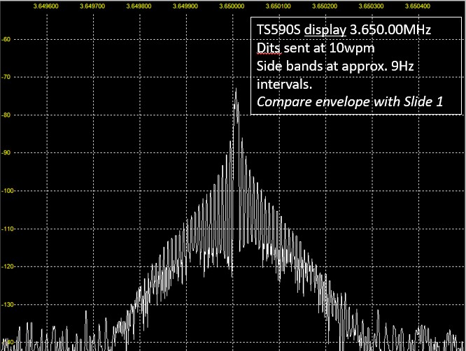
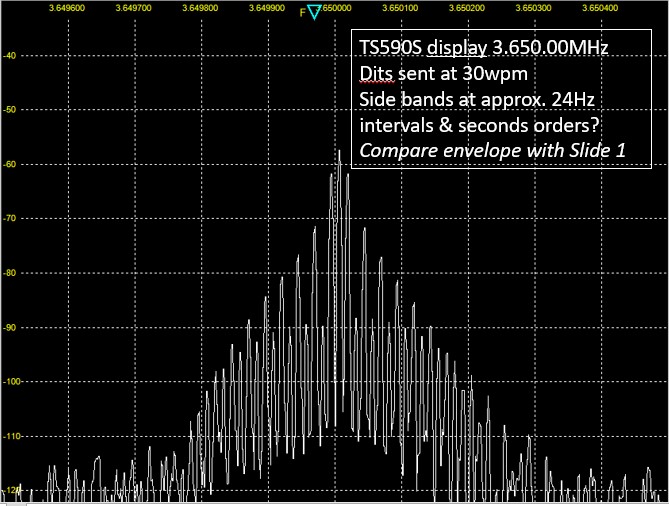
That’s well illustrated by comparing the spectrum analyser plots of a ‘continuous dots’ CW emission from my friend [G8EJN] on his TS590 for two cases: 10wpm and 30wpm.
The ripples in the sideband envelope change with increasing dot speed but the bandwidth is about the same for both, i.e. approx. -30dBm down from the carrier at +/- 100Hz from the carrier frequency and approx -40dBm down from the carrier at +/- 200Hz.
It seems each sideband is about 100Hz wide [depending on your chosen definition of bandwidth] so I guess one could go as close as 100Hz to a band edge as you say. But, as you also say [and as I previously stated, and at the risk of more objections] my natural caution would be to guard-band my CW Tx a bit more, to 200Hz, to allow for these other factors.
A point of terminology Andy. Dbm refers to an absolute power level referenced to a milliwatt. So 0 dbm is 1 milliwatt, 3 dbm is close to 2 milliwatt, 20 dbm is 100 mW.
Where you want to say a particular signal is 20 db below another you just use db as the reference level is defined. If referencing a defined carrier you use dbc.
Andrew, thanks for the clarification and reminder on the usage of those terms.
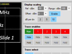
When I wrote that post I glanced at the plot scaling, saw “dBm” (for Ref and Range), which was in my head then. If I had been less hasty I might have noticed “dB per div” just below it which would have reminded me to express the difference between levels in dBs.
Your plots very nicely illustrate what was said above. I think they also say that the keying envelope on that TS590 is easily sharp enough for the very highest human-readable speeds. For those of us who struggle with 30WPM () a gentler keying envelope (if available) would happily accommodate our lower speeds and result in a reduced bandwidth.
 ) a gentler keying envelope (if available) would happily accommodate our lower speeds and result in a reduced bandwidth.