Had a similar problem with the T1. The T1 has a mode where you can switch every single relay separately and check. However, sometimes it can be as simple as a broken inner part of a connector… Good luck in fixing the T1!
73
Ingo
Had a similar problem with the T1. The T1 has a mode where you can switch every single relay separately and check. However, sometimes it can be as simple as a broken inner part of a connector… Good luck in fixing the T1!
73
Ingo
Stephan,
Your consideration is probably a hasty shot, as it makes no relation to the frequency range to be covered.
In other words, large steps of L and C are just as useless in the higher frequency range as small steps in the lower frequency range.
The choice of the discrete values for L and C and the number of LC elements must therefore be carefully coordinated for the intended frequency range - as is the case with the antenna tuners for the 3 Elecraft products mentioned below (sorry again, no business relationship with Elecraft, hi).
If the dimensioning of the L network elements is chosen inappropriately, inventors of tuning algorithms will forever praise new, supposedly improved tuning algorithms, guaranteed …
I do not know from which original and to what extent the hardware and firmware of the ATU-10 variants offered on ebay were originally stolen.
73 gl, Heinz
As a supplement, the 3 Elecraft Antenna Tuners that are often cited and used in so-called ATU comparisons
For the expert it is obvious that and why these 3 Elecraft ATUs cannot be exactly compared with each other:
T1 (1.8-54 MHz)
7 inductors and capacitors (max. L 7.5 uH, max. C 1300 pF)
KXAT3 (1.8-54 MHz)
8 inductors and capacitors (max. L 15.93 uH, max. C 2683 pF)
KXAT2 (3.5-30 MHz)
7 inductors and capacitors (max. L 7.887 uH, max. C 1323 pF)
Hi Heinz,
Thanks a lot for your valuable input!
Yes, that’s what I also thought about. In our quick test with @DL6GCA I observed a strange anomaly: By resetting the tuner and starting from scratch, it could find an acceptable match. If I recall correctly, this happened on two bands. We tried all bands from 60m to 10m.
It would be interesting to know the steps of the KX2 internal tuner, for example.
The ATU-10 has the following values:
L = 0.1, 0.22, 0.45, 1, 2.2, 4.5 and 10 uH (max. 18.47 uH)
C = 22, 47, 100, 220, 470, 1000 and 2200 pF (max. 4059 pF)
Thanks also for providing the max. values for the T1, good to know!
73 Stephan
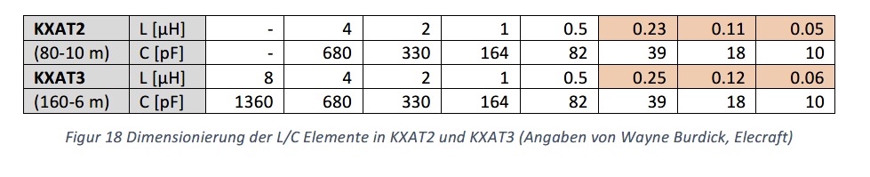
Below is an overview of the L&C values of the KXAT2 and KXAT3 (copy from an older document in German).
What was remarkable for me at the time was that the KXAT2 was able to perfectly match the high impedance of my multi-band inv-L on 10m, while the KXAT3, in the very best case, only achieved an SWR of 3.5 … and this despite the 3 smallest L&C values both ATUs have identical values.
My conclusion at the time was that in the KXAT3, due to the less compact design compared to the KXAT2, additional capacitance had to be introduced, so that the minimum effective total capacitance is significantly larger than the smallest selectable value of 10pF.
From this point of view, the minimum selectable capacitance of 22pF on the ebay ATU-10 seems “astronomically” high to me, hi. And if you add the inductor values, there are some gaps that can be relevant in the range required for “common” portable antennas.
This might be an explanation. Or diverse component tolerances in both TRX. Or better matching algorithm in the KX2.
Seems like. The same applies to the min. L of 0.1 uH. Both values are about factor two compared to Elecraft.
I just checked the ATU-100 that is of similar design (100W version, also from N7DDC) and according to its schematic diagram, its values are similar to the ones of the KXAT2.
The ATU-100 has the following values:
L = 0.05, 0.1, 0.22, 0.45, 1, 2.2 and 4.4 uH
C = 10, 22, 47, 100, 220, 470 and1000 pF
BTW: David (N7DDC) explained to me: “…the SWR should be below 10 for normal tuning algorithm operation, because the tuner is not able to measure SWR more than 9.9…”. I interpret this statement that the ADC with SWR > 9.9 is at its limit (overflow), but that’s just my guess.
73 Stephan
Most of the Little MFJ tuners are gone now.
72, VE7VIE
The Chinese one is on sale now at BG. I just ordered one. My Elecraft T1 died, and any replacement would be $250USd.
ATU-10-0A 20W 1.8-50MHz Mini Automatic Antenna Tuner OLED Display Aluminum Alloy Outcase with1800MAh Battery ATU Antenna Tuner.
Total: CA$99.60
Tony Albus and many others on YT have reviewed it.
72, VE7VIE
I use Elecraft T1 with HB-1B and SW-3B.
No complaints.
73, Jarek
I use the mAT-10, it was € 140 when I got it two years ago, but its price got unreasonably high since then.