Anyone tried deliberate NVIS on 40 or 80 ?

Heinz,

The graphs show that most of the radiation is sent upwards.

The strength starts falling at angles of under 45 degrees.

There is no radiation towards the horizon.

The radiated signal is more than 10 dB down at best.

If the ionosphere is at 300 km the best signals will typically be at around 420 km unless the MUF is favourable.

If the ionosphere plays nicely NVIS over short paths will be good.

73
Ron
VK3AFW

1 Like

There is a lot of very useful material on this thread.

2 Likes

I have made a number of semi-local contacts on 20m. A contact is an observed fact. Ascribing it to any mode of propagation is a hypothesis. Naturally one firstly thinks of NVIS, whilst this seems unlikely it is not impossible that some unusual circumstances may have come into play to permit what seems to be near vertical incidence, perhaps that is more likely than say round the world propagation! The point is that these anomalous contacts do occur, they are observations not myths, and as such they need explaining. I would point out that NVIS is not a mode, it is a geometry, there may be more than one way that this geometry may be effected.

2 Likes

I disagree. With that argument one could say using ground-wave or [lower angle] skywave are merely ‘geometries’ and label them Near Horizontal Wave and Acute Angle Skywave.

NVIS like these two are modes of propagation in that the operator is - deliberately or unwittingly - exploiting where the bulk of the tx’d RF energy is going for effective communication.

Semantics maybe but important for correct understanding and classification.

1 Like

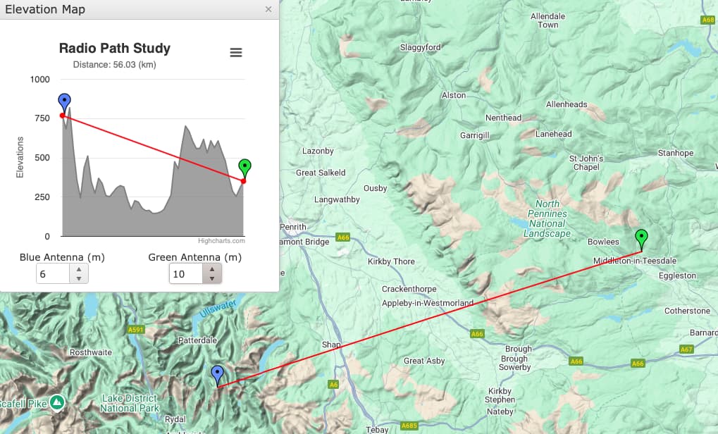
I live in (for radio) a fairly rubbish location in the North Pennines - Rubbish in that despite bring 340m ASL there are bigger hills in almost every direction. When the sun was less active (2021) I had several QSO’s with Mark M0NOM on 20m SSB (so there goes another 10dB) that were workable (55) but not strong signals. It would be interesting to try and find the propagation mode. I don’t think it was aircraft scatter as the signal was too consistent and I notice that one of the QSO’s was December - so possibly not Sp E? . The one I have mapped was to Stoney Cove Pike on 31-03-21 @ 9AM. Looking at the map the signal would seem to pass over or at least near Mickle Fell, a sort of green boggy summit so no sharp edges that might cause diffraction. (Antenna is relative to hams that can get a tower in the garden relatively low at about 11m, and just a wire antenna not a 6 ele beam)

Any Suggestions of possible modes?

There are a number of possible explanations for such paths, especially when one cannot rotate a directional antenna to determine the actual direction of arrival of the signal.

For example, backscatter is often used to work nearby states for WAS on 10m. There the signal may be reflecting off ocean waves over 1000km away, sometimes to the side of the direct path, and returning with enough strength to make a contact.

While we don’t often think of ground wave on 20m it isn’t impossible to cover 50 km using that mode, depending on power and the ground conductivity. Generally that would be limited to vertical polarization at both ends.

Direct propagation via reflections, as we often encounter at VHF, is also possible at 20m. If there is a tall enough peak behind the receiving station, then there may be a direct path between it and the transmitter, then the signal is reflected off the peak down to the other station. And there is no need for the reflector to be in the direct line between the two stations: it could also be off to the side, for example, a hill reflecting a signal around a corner into a valley. Anyone who has hunted hidden transmitters on 2m has probably experienced how quirky such paths can be in hilly terrain.

So I wouldn’t worry too much about the actual mechanics of the path, especially with non-directional antennas. Just log the contact and move on to the next one, and appreciate the idiosyncrasies of propagation.

2 Likes

Ron,

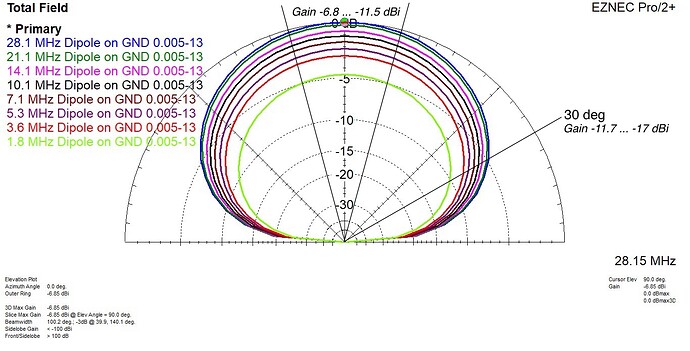
You probably overlooked my stated motivation to find an answer to the question I asked myself: what must be behind it when SOTA enthusiasts report successful portable radio operation with wire antennas laid out on the ground only - and assume that this is possible because of the steep radiation angle (NVIS).

My primary interest is in the extent to which losses due to the (nearby) ground affect the antenna gain. Because EZNEC assumes perfectly flat ground (like Wimbledon’s lawn, hi), and the actual ground at SOTA summits is generally uneven and interspersed with larger objects (e.g. tufts of grass, small bushes, large boulders), the calculation results can only be considered estimates (worst-case scenario, though).

As can be seen from the EZNEC plots, the losses increase with decreasing frequency and are by far the greatest at 160 m.

The calculated gain of such a dipole is at radiation angles of
– 30° between -11.7 (10 m band) and -17 dBi (160 m band) and
– 90° between -6.8 (10 m band) and -11.5 dBi (160 m band).

Due to the factors influencing NVIS radio paths known from scientific studies as well as commercial and military projects, and excluding Sporadic-E, only the bands below 30 m are relevant for my question.

The question remains as to the required transmit power under these conditions for the two cases mentioned above (path loss is frequency-dependent).

Is there perhaps an online calculator for this somewhere?
.
.

1 Like

The biggest uncertainties are the D-layer absorption and the actual ground conditions.

The D-layer absorption is why 160m is often not open during the day. It is higher at lower frequencies, and tends to reduce at night (although at high latitudes the D-layer may still be in sunlight when the Earth below it is in darkness).

I’d suggest using VOACAP (which runs online) for such an analysis: it provides a probability of a path being open vs. time of day, and you can specify a power level and antenna type (although from a limited number of options). But if you can look at the results for a height of 5m, for example, then you can extrapolate to a lower antenna using your results from EZNEC. It can account for Es, but not for other scattering or reflection modes. You can even provide your own antenna pattern files to it, although I haven’t tried that approach.

The actual ground conditions vary with frequency. One issue is that mountaintops often don’t have the same sorts of soil types that we might find in other areas. Here in Oregon, where much of our soil is volcanic (a friend lives on an old lava flow, with virtually no dirt, and other areas have thick layers of volcanic ash), conductivity tends to be very low, and the RF may permeate further into the ground. In that case, the effective height above ground may be greater than it would seem. (A ham in Nome reported laying his antennas on the ground, as they had 30m of dry sand that acted as an insulator.) So the “standard” ground conductivity values might not apply. Snow and tufts of grass also have an impact: even 10cm of height can make a difference in efficiency.

Based on the number of hams who have made contacts using milliwatts, we know that it doesn’t require a lot of power in good conditions. In one exercise, I was using an 80m dipole in a parking lot, with the center 2m up in a tree, and most of the antenna running along a low hedge at about 50cm off the ground. We clearly copied another station using a dipole made from a pair of mobile whips, with their FT-817 in high SWR shutdown mode. True, they weren’t moving the S-meter, but they were perfect copy.

So I don’t think any calculator is going to be accurate without being able to model all the variables. The best approach would be to set it up on some of your favorite peaks and try it out with another station, reducing your power and seeing how well they can hear you. Expect the resonant frequency to shift around at low heights, so you may need a tuner.

Also, I hope you are using the NEC 4.2 computation core for EZNEC for wires laying on the ground. The more common NEC 2 core is not accurate for wire within about 0.05 wavelengths of the ground.
1 Like

There is a second weaker Es season in December and January.

Same conclusion here, so let’s leave it as it is.
Thanks for sharing your perspective!

1 Like

Brad asked the question, and had almost 30 replies. Hours of time, spent by enthusiasts making their own point, experience, suggestion or theory. LIttle response from Brad who asked the question
 maybe there will be a response or a word of thanks for the advice!

You see this so often on these reflectors. The questioner spends little time asking the question rather than researching the subject him/herself and then hours are spent by folk replying - that is social media for you I guess.

73 Phil G4OBK

2 Likes

Slightly OT - I’m known for nit-picking, so I’ll go ahead and insert a comment on some statements made in the PDF document from Carolyn G6WRW, which I think might be of interest to some. A couple of references are made in the PDF to a wire “velocity factor” when calculating the lengths of wire used in the construction of Carolyn’s two-dipole antenna.

Firstly, it has to be said that the notion that antenna wire would have a velocity factor has been discussed, and thoroughly demolished, in other threads in this forum. Simple antenna wire - regardless of its’ type (solid or stranded), or material (copper soft or hard-drawn, copper-coated steel, etc.), or whether it’s insulated or not - does not have a velocity factor, unlike coaxial cable, with its’ more complex construction and arrangement of different materials between conductors.

Various other factors, however, do come into play when constructing such an antenna: these are combinations of factors which depend on the antenna’s wire diameter and thickness of insulation, wavelength, height of antenna AGL, and in the case of an inverted-Vee dipole, the apex angle of the antenna. These factors are:

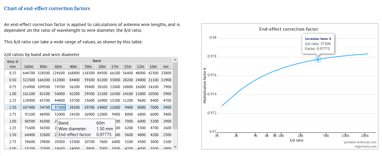
  • end-effect: this is dependent on the ratio of wavelength to wire diameter - the λ/d ratio - and for the typical range of wire diameters and wavelengths of interest to ham radio, has values between 0.9737 (6m band, 3.5mm dia.) and 0.9785 (160m band, 0.25mm dia.). For the 60m band, and 1.5mm diameter wire, the factor is about 0.9778. This factor is applied to the final 1/4-wave section of any antenna with a free end, so applicable to (each leg of) the dipole discussed here. The factor would not be applied, for instance, to a closed-loop antenna like a delta-loop.

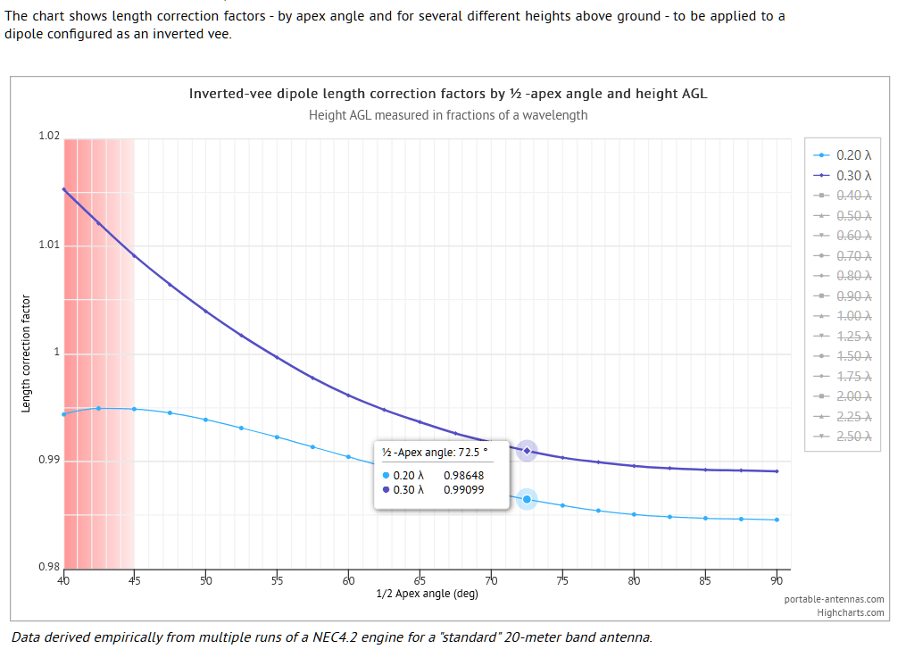
  • height of antenna (feed-point) above ground level (AGL) and apex-angle: these two have more effect on the impedance of the antenna than on the wire length. The antenna in the PDF is pretty low compared to the wavelength(s): no pole height is given, so an estimate of 6m height AGL is taken, which turns out to be 0.1 lambda or even less at the wavelengths covered by this antenna. The apex angle is also not given in the PDF, so an estimate of 70° to 75° is made from the diagrams provided. At such a height and apex angle, a multiplicative factor of maybe 0.99 is guesstimated from this chart, derived from NEC simulations (the chart doesn’t reach down as far as 0.1 lambda, since the NEC engine cannot accurately calculate radiation patterns at such low heights AGL):

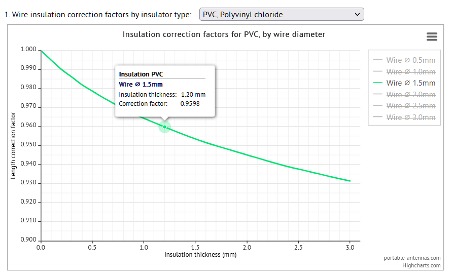
  • wire insulation: this has a much more tangible effect on the final length of the wire than the other two effects. The 4mm Flexweave wire used has a wire diameter of 14 gauge, or about 1.57mm, and an outside diameter (including PVC insulation) of 4mm, giving an insulation thickness of about 1.2mm. As the chart shows, this results in a shortening factor of about 0.9598.

Multiplying each of these factors together:

0.9778 x 0.99 x 0.9598 = 0.929,

which compares reasonably well with Carolyn’s estimate of

0.95 x 0.96 = 0.912.        

As ever, adding a few percent to the calculated length is always a good idea to give enough leeway for cutting the antenna to its’ final length. And as usual, YMMV


Cheers, Rob

1 Like

Definitely a nitpick “velocity factor” “shorting factor”.

The original question was had “any of you tried a deliberate set up for NVIS (Near vertical incidence skywave) on 80 or 40 meters was it any good?” so as I had a lot of practical experience I replied.

I rarely use my dipoles now I moved on to verticals as they are easier to deploy and take up less space.

Carolyn

1 Like

This reminded me that I optimised the height of my doublet for 60m NVIS when I was issued my NOV for experiments on that band back in 2005 and have not changed it since! A 40 metre long doublet has worked well for me on all bands 160m to 10m so there has been no reason to change it.

I’m sorry, Caroline, in my efforts to clear up any misunderstandings about velocity factors, I had neglected to give your work on your twin dipole antenna the praise it deserves. It’s a good article, and I’m sure the antenna will have functioned very well.

And yes, I’m aware of the original question starting this discussion, which is why I said “Slightly OT” as preface to my remarks.

Cheers, Rob