A Versatile Tuner for SOTA Activations by KX0R

Thanks for your time George!, Definitely I will need to tune on 21MHz diferent impedance values; my goal is tune 40/20/15m bands in order to use my direct conversion QRP

Sorry is in spanish.

I thought solving the big capacitor issue by switching the coil… but I didn’t think on the low impedance situation! You are absolutely right and I glad to have asked for your opinion.
I have a second pole on the same 6 pos switch and I imagine the next circuit, but maybe I will loose flexibility to choose hi and low frequency over the total lenght of the coil to match high Z loads on higher frequencies.

This is the beast so far:

3 Likes

Alejandro,

Using two sets of switch contacts is an interesting idea. You have many possible combinations! I think if you build it and experiment with your tuner and antenna outside, perhaps at home, you can choose the right taps on the coil to get matches on several bands.

Your work looks really good! Please come back after you do some tests, and show us what you have decided - it may take several attempts before you get good matches on several bands, and everything depends on your antenna and how it is fed.

Here in Colorado I use the RBN (Reverse Beacon Network) to see if my CW signals are being received by many stations. I also look at the spots for many other activators. There is a very wide range in the efficiency of activators, and which bands they do well on.

Spot signals vary greatly on the RBN, so these results must be used in a general way, but lots of spots and strong db reports indicate good results. Few spots with low db numbers indicate that most chasers will not copy you on the particular band you are on.

Even with a wire only 3M high, 1/2 wave long, and a transmitter of 5W output on CW, on a hill or mountain, some RBN spots should be higher than 10 db, for 40-30-20M. There should be many spots, if you call CQ for 5 minutes or more. This is approximate, but many stations are doing a very poor job!

73

George
KX0R

4 Likes

Well, today I’ve been finishing it and running a few test…not “on the air” ones yet; but just trying with resistors using the first circuit.

I’m very happy with the results, since I was been able to tune a 5K from 3.5 to 28MHz, and after that I start checking how low can the resistor be; so the second test was on 470 Ohms and I could tune it over the same range of frequencies. After that I tried with a 50 ohms resistor and the circuit could tune it only from 14Mhz and above.

Now I can use it with End Feeds; near 450 Ohms to the 3000-5000 Ohms of a EFHW. Tomorrow I’ll see another configuration to check if I could tune from 100 Ohms or less on the lower bands to use it with coil loaded verticals or something similar.

73!

3 Likes

After a few tests I will say the original circuit was my choice to use with my 20m wire!.
It tunes from 6 Ohms to 5000 ohms resistors from 40 to 10m bands; I’am really happy with the tunner.

Last weekend (3/11/19) I used it successfully at the LUM/PC-043 activation; and will use it on my next activation too!


Thanks for your patience George! 73!

5 Likes

Alejandro,

You have done a good job! I think you will like using that tuner. It’s fun to change bands without having to change links on the wire.

You may want to make an antenna with links or jumpers, so that all the bands will be resonant and high-impedance. I did this for a long time. You only need one link in a ~20M wire to have 40M, 30M, 20M, and 15M be all high-Z. 17M will also be close to high-Z resonance if you open the jumper for 30M. The one link will be at the point where the wire will be tuned to a half wave for 10.1 MHz. My tuner will tune the 20M wire without using any links, but it may work a little better with one link for 30 and 17M. I have never done tests to determine if the link improves efficiency, but it certainly is easy to tune up on 30M and 17M with the link open.

Exact resonance is not important on any of the bands - the tuner will correct the reactance if resonance is not exact.

I am glad to see your work, and now I have happy that I wrote the article about the tuners. Hopefully as others work with these tuners, perhaps improvements will be made, and people will share what they learn.

73

George
KX0R

2 Likes

One thing to be considered, applicable to some of the simpler designs, is to use an N-turn Faraday shielded link instead of just N-turns. As many may know, this allows better isolation of the rig from the tuner / antenna, makes the antenna use the counterpoise instead of the rig, etc. see PIX: this is a 2-turn example, coax from the rig not connected to anything except by inductive coupling.

Best, Ken

5 Likes

Ken,

A picture is worth a thousand words!

I’m aware of this idea, but the way you did it here is sweet. The series capacitor can still be used in the ground side of the coax primary wining at the point where you show the soldered connection.

Should the shield braid ends be connected together near the cable tie, or one end left unconnected as you show? If they’re connected together, it’s a two-turn shorted winding, so I think we don’t want that. This is important to remember, since we often connect shield braids together and to ground.

I should do some work with this - simple prototype - and see where it leads. Great idea!

I don’t really know whether the unshielded primary makes much difference to the signal that radiates.


When I contacted you today on 40M, I had broken several feet off my antenna wire, because it got stuck in a bush - stuck too tight to pull out - and it parted. My tuner tuned it up easily, so I didn’t try to repair it up there on that wonderful pinnacle. After I had worked 9 stations I looked at my 12-foot counterpoise lying on the ground, and realized that it wasn’t connected to anything - forgot to plug it into the tuner.

The antenna had 52 feet of wire on 7.063 MHz, end fed, inverted-L, with only a few feet of wire (2 feet of RG-316 coax, headphones, key cable) attached to the ground side of the tuner, working almost as well as the resonant end-fed half wave I usually use on 40M, but with a much lower impedance and quite reactive. I was on a mountain top that’s mostly rock, so go figure how it worked so easily. When I plugged in the CP, the tuner settings needed to be changed considerably, so the CP was carrying significant current once attached.

With resonant half wave wires, I can disconnect the CP, and the tuning scarcely changes at all.

Lots of surprises occur, but plenty of work will be needed to see how important counterpoises are in various situations.

73 for now -

Carey/George
KX0R

5 Likes

Ken,

I just looked at my RBN spots for today, and based on those spots, on this rather quiet day (no obvious magnetic or solar disturbances), it would be easy to claim that a 52-foot end fed wire, tuner-fed, works as well on 40-30-20M as a 66-foot end fed wire, regardless of whether a counterpoise is used or not. All three bands look pretty good - sure wish all the activators I try to chase had spots like these…

73

KX0R

3 Likes

George,
Re: The RBN spots: INDEED! That said, it’s the propagation Gods that are really running the show!

Re; The Faraday shielded link, the coax center conductor end is connected just to the shield.

The example shown was the means of feeding two 4-foot whips butted (and connected) together.
The whips were horizontal, at about 5 ft. above ground; the coil resonated them on 20M. The coil went from that junction of whips to the base of a 17-foot vertical wire. The 2-turn shielded link was the coupling to the rig. This resulted in a very light (albeit just for 20M) antenna that collapsed for carrying in a pack. It was made for use on a summit without without much area or supports.

1 Like

Hi Folks,

After two years using a 40-15m EFHW trapped antenna for SOTA activations, this past autumn I started to looking for a more light and flexible antenna solution.

Discussing the options with Ignacio EA2BD he reminded me of this thread, then, after reading the detailed information and interesting comments I decided that George KX0R tuner would be my choice to build.
As chaser and after more than hundred SOTA QSOs with him I can say that his signals are always good in this part of Europe.
Also, lately I like very much to chase in the 60m band and find that (among others) one of the EU activators I have heard always in good shape on that band is Bruno HB9CBR/P, then I asked him about his portable setup. Bruno kindly gave me the details of the station he use over the summits which are are as follow: Elecraft KX2 with internal ATU and the antenna is a 11.2 meter long wire with a 1:4 UnUn and 4 radials, each 4.25 meters long. It was built and designed by Heinz/HB9BCB. The antenna is used as inverted “L” in a 6m flagpole. As Bruno comments, for multiband use the antenna tuner is a must .
I was facinated to know that his small antenna can produce such good signal on 60m!
This definitely convinced me which antenna and tuner combination I had to build.

TUNER

With 60 to 15 meter operation range in mind and always using my KX2, my goal was to simplify the construction, then, I removed the swr bridge, some switches and aditional capacitors. But, instead I put one rotary switch like Alejandro LU1MAW .
I have not made any changes to the original design because if something goes very well, why to change it!! Below my ugly drawing:

CONSTRUCTION

I have used some parts from my “junk box” like rotary switch, 500v silver mica fixed capacitors, toggle switches, etc. I found an appropriate plastic box here:
https://www.amazon.es/gp/product/B0056BPPCQ/ref=ppx_yo_dt_b_asin_title_o08_s00?ie=UTF8&psc=1

I have replaced the top cover, with one made with PCB material, to keep room for the rotary switch + toroid core height, it fits on top of the box, this way I get 7mm more in depth.

The toroid core is one T106-6 that I have bought here:

https://www.ebay.co.uk/itm/252936360808?ViewItem=&item=252936360808

The winding is the same as George ones (3+3 turns primary and 16 turns secondary)
I added one small piece of pcb to the back of the rotary switch and secured the toroid to it by double-sided adhesive tape . The whole set is perfectly secured against the bottom of the plastic box.

Polyvaricon variable capacitors are from here:
https://www.ebay.es/itm/2-pieces-Variable-capacitor-Polyvaricon-Tuning-Tuner-QRP-160-70-pF-Ham-Radio/303115701652?hash=item46931a8d94:g:ZpIAAOSwmNlZZPZs

They have 6-160pF + 4-60pF sections and comes with 6mm diameter metal shaft extension ideal to fit tuning knob. As George advises for safety I do adjustment at low power, when match is found caps admit the full 10w power from KX2 without any problem.

RESULTS

First time bench test show that it tunes from 20 to 4.300 ohms in the range of 60 to 15M band. Then I went to the field for RBN test with the same wire sizes of Bruno HB9CRQ antenna (11.2m inv “L” + 4x 4.25m radials) , concentrating in 5 to 21 Mhz bands, the most difficult band to find match was 7 Mhz, but reports on RBN were satisfactory in all bands. The next step was to make an activation with this new antenna + tuner setup

For the occasion I went with Ignacio to EA2/NV-032 Artxueta, you can read full report here:

https://reflector.sota.org.uk/t/fighting-the-wind-in-ea2-nv-032-mt-artxueta/21759

Weather was sunny but with a very strong and gusty wind which tested the strength of the new antenna that resisted perfectly. I worked 60, 30 and 20m with good results, but was a little dissapointed because I could not match in any way the 40m band!! Perhaps I made a mistake selecting T1 tap ?, as the antenna is near quarter wave on this band his Z (according MMANA simulation) could be near 50 ohms, then, should have used 1:1 tap for T1 ? I never did more test to confirm this teory…

Instead I cut a new radiator wire at “random” size of 41feet or 12.5 meter and keeping the 4 x 4.25m radials system I made field test of this new antenna, matching this time very easy from 60 to 10M with good RBN reports as well. 20M show a very “sharp” tuning.

For comparison with one EFHW Ignacio and me decided to activate EA2/NV-151 San Martin, full report here:
https://reflector.sota.org.uk/t/validating-a-tuner-at-mt-san-martin-ea2-nv-151/21888/2

Activation was in a pleasant afternoon and we were on the summit until near the sunset, this time I could match in all band bands with DX QSOs on 20m too and excellent signals reports in 60M from Europe, just before QRT I tried to match 80m and it was possible at 1.5:1 swr, then called CQ few times in this band and one RBN in OK report me at 8dB We returned home very happy with the results…

Future steps

Perhaps I could add more capacity on the output capacitor for better SWR in 80m but 1.5:1 is not so bad isn´t it? Also, I could do more tests with the 11.20M wire to match it in a reliable way on the 40M band. In any case this is an always open project.

Acknowledgement

I want to express my thanks to George KX0R for sharing with us comments and construction details of this excellent master piece which is his tuner design.

I enjoyed a lot building it and I´am very happy with the choice, this has given my portable station more flexibility and less weight.

See you all on the bands as a chaser or activator.

Best 73

Jorge

EA2LU

6 Likes

Hello Jorge,

Congrats on your nice ATU project.

Re 11.20m inv-L antenna:
At an apex height of 6m my antenna is resonant at approx. 7100 kHz (SWR 1.1 on the antenna analyzer), so no need to make something worse, hi.

BTW, The 1:4 UnUn used by Bruno@HB9CBR was just a makeshift, in the target solution (currently in test), only the (electrical) wire length is varied for the bands the KX2-ATU needs some help.

73, have fun!

Heinz

2 Likes

Nice work George! Ive been looking for a match for a 60m antenna and there it is. Im building a 60/40/30m trap end fed half wave and needed a match for the 60 m frequencies. My matching unit for my 40/30/20m trap EFHW doesnt cover 60 m. Thanks for sharing your work with us here. Look for you on the bands again George!
73 GL SOTA
Mike NS1TA

All,

I’m delighted to see so many of you trying out the concepts in my article. Using a rotary switch to select taps is great, and I see good work in your pictures!

These tuners are fun to use on the air. After a while you will see differences in the ideal matches depending on how high your wire is, what it is near, or where the far end is located.

Sometimes it’s fun to take more than one type of wire antenna and compare the performance using the RBN spots, noise levels heard, or reports from chasers.

There are so many easy ways to put out a good signal - I wonder why people use short or tiny antennas, etc. An end-fed wire on a fishing pole is incredibly easy to enjoy on many bands!

The basic tuner designs I presented work well with the high-Z antennas like the EFHW, but these tuners work well with a 1/4 wave vertical and a couple of 1/4 wave radials also. This is a low-Z antenna, roughly 50 ohms at resonance, so you must provide an output tap low enough on the tuned circuit for a good match - be sure to include a range of taps - tuning into such an antenna, or a center-fed dipole, is just like tuning into a resistor! Very broad match!

Even though the basic tuner design is unbalanced, low-Z balanced antennas like dipoles can be fed with these tuners without any real problems. The balance will not be as perfect as with a balanced tuner, but you’ll have an easy time making lots of contacts.

73

George
KX0R

4 Likes

Hi Heinz,

Thank you for your comments as “father” of the 11.20m inverted “L” , yes! I agree with you that the antenna resonate in 40M band or very close in my case. As I said MMANA simulations that Ignacio EA2BD and myself did show his resonance at 6.719KHz but, without the 1:4 UnUn.

Then, last Firday morning I went to our contest place (close to EA2/NV-092 summit) bringing my AA200 antenna analyzer and SOTA backpack to test again the 11.20m antenna configuration.

I made some measurements directly at the feed point wires of my (your design) antenna

In the photo you can see the results:

In my fishing pole the apex is about 5.5 m high and the 4 x 4,25m radials were laying in a “Pastoral, medium hills” soil type, different to “Rocky soil/mountainous” that we ususally have at the summits, so that there isn´t big difference.

My goal is to tune the antenna with Geo´s tuner directly without the UnUn, but again, I couldn´t find the right combination in 40M, the best SWR I got was 2.5:1, It seems my tuner need to add more capacity on the input circuit. It is a simple task that I will do soon.

Heinz your antenna is an excellent performer from 60 to 15M as I could check in the EA2/NV-032 activation in Dec 2019. The downside is that I can´t match it with my own tuner without adding the 1:4 UnUn, but, sooner or later I will do it.

Now, Thank you very much for the QSO we had on 60m from summit HB/FR-047 last Friday afternoon signals here from your 11.20m INV “L” were loud 599!!

See you on the bands, and thanks for sharing your experiences with us .

73s

Jorge

EA2LU

1 Like

Hi Jorge,

Thanks!

As George@KX0R stated above your antenna matcher should provide a setting for low-z antennas.

The easiest way to add such a feature would be to replace the existing S3 (on-on) by an on-off-on switch, with the existing 160 pF connected to one side and the existing 60 pF to the other side (to take all the capacity out). Low-Z antennas should then be matchable on rotary switch positions 4 and/or 5.

Yes, increasing the apex (away from earth) makes the wire electrically shorter, which increases the resonance frequency.

73 have fun,
Heinz

All this spare time at home leads inevitably to finishing off the kits lying about in draws here and there. After my Fuchskreis got blown down the mountain in Iceland one too many times, I decided to give it a complete overhaul using parts from another kit I bought. I have decided to try and squeeze it into the same size enclosure (70mm × 50mm × 25mm), rather than going for the next size up. To do this, I have shortend the connections to the toroids and repositioned the variable capacitors to the sides of the enclosure rather than the top:

Obviously, the variable capacitor is pointing in the wrong direction at the moment. When the kit is finished it will face outwards and the other variable capacitor will stick out the opposite side. There will be a bit more clearance when the new enclosure gets drilled.

    73 de OE6FEG
                 Matt
2 Likes

George,

Thank you for many S2S contacts!
No I understood why it was possible.
How about publishing this material in QST or other amateur radio magazine?
This tuner concepts may be interesting not just for SOTA forum members, but for any QRP lovers.

73! Oleh

4 Likes

One if the best threads on the reflector. Thank you again George.
73 de OE6FEG
Matt

2 Likes

Oleh,

Thanks for your comments!

The QRP Quarterly published my article last year. It also was published in Spain with a few additions.

It’s still here online, which is nice. A few people have built similar tuners that work well, and that is what I hoped would happen.

My larger tuner works well down through 60M, and up through 15M, but I need to build some new tuners for higher frequencies and lower frequencies. When the sunspots return, great times await, perhaps on 10M with easy DX during the day.

With the virus crisis, this is a good time to stay home and build tuners and other gear for SOTA!

73

George
KX0R

4 Likes

Just finished the toroids this morning:

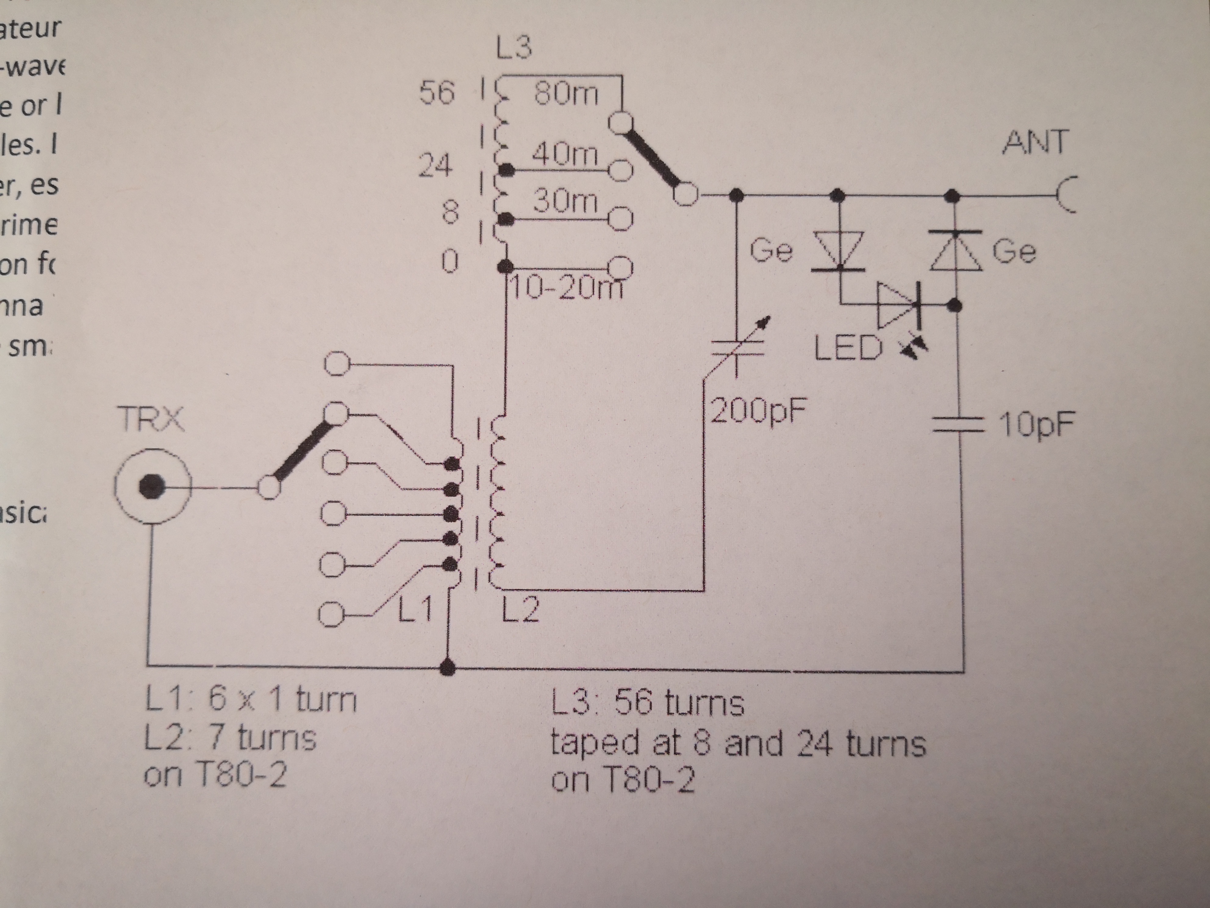
I used L3 as is from my old tuner, just shortened the leads a bit. However, I wanted to rewind L1 and L2 (coupling toroid) to get the windings as tight and neat as possible. I also left longer leads to get to the additional variable capacitor between L1 and ground.

Other improvements include shaping the holes in the enclosure with a file so they have flat sides to grip the switches and BNC. I’m trying to think of a way to improve the connections between common on the switches, and the input and output. I’ve plenty of time to think it over.
73 Matt

4 Likes