Andy,
Thank you.
Here’s PART 2, with the actual circuits I use for SOTA activations. This part is for those who are interested mostly in building a tuner to use.
ACTUAL KX0R CIRCUITS
Here are two KX0R tuners showing the actual circuits. This is not a how-to-make-it article – experience and improvisation are required.
For best performance, these tuners should be compact, and small wire should be used to reduce capacitance. I suggest wire-wrap wire, or small single-conductor silver-plated Teflon wire. While a PCB could be used, it likely would add capacitance, which adversely affects these circuits at higher frequencies and high impedances. The output impedance may be several thousand ohms, where every pF is a problem – this is the opposite of working with 50 ohms.
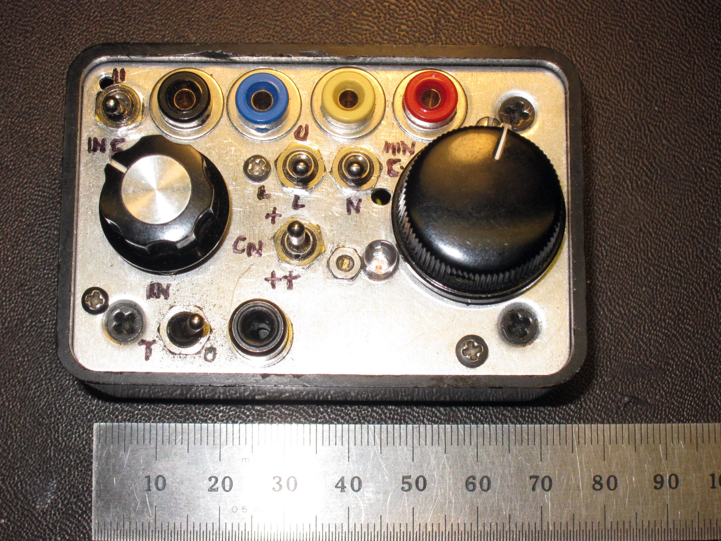
THE LARGER TUNER:

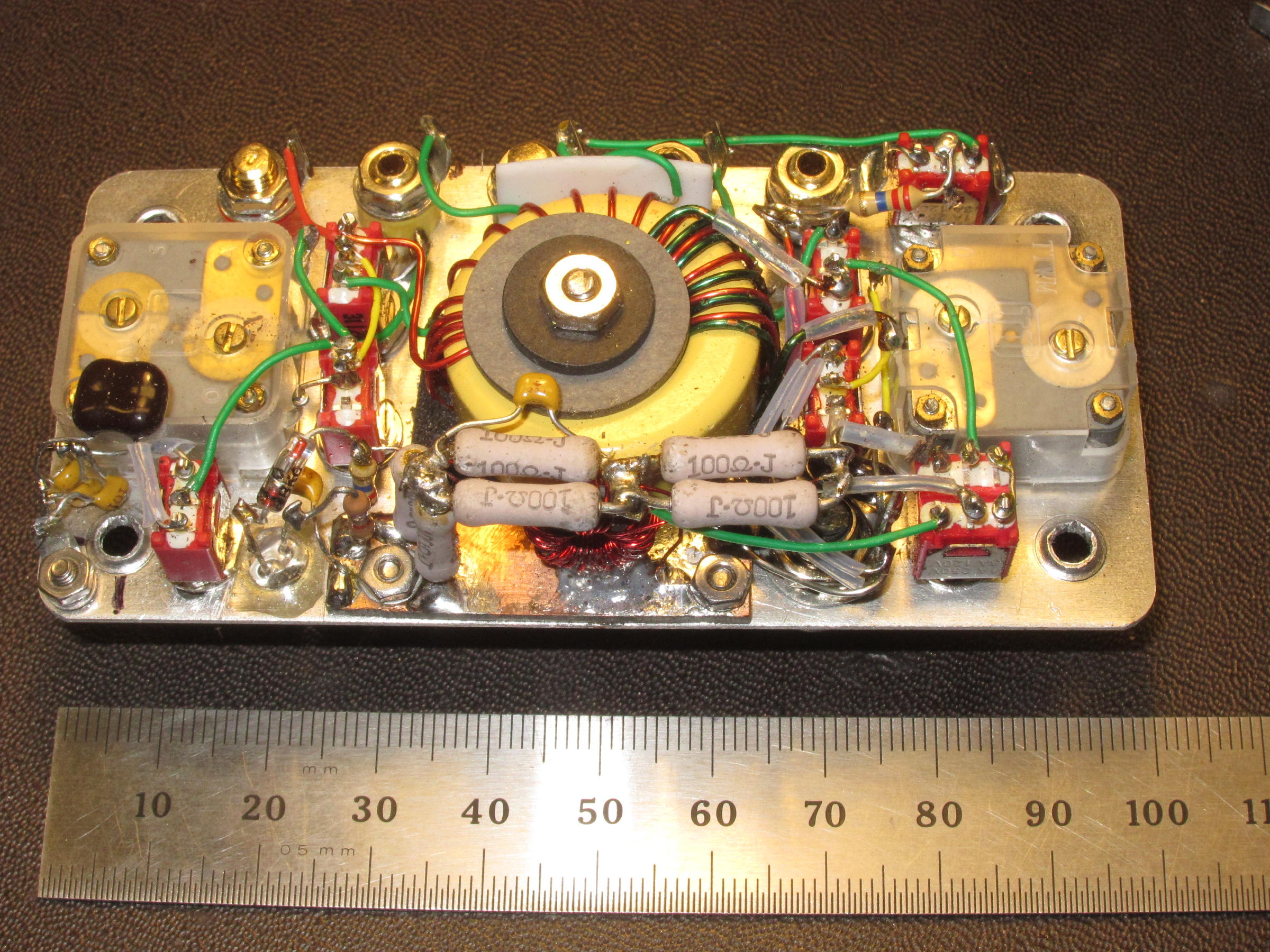
THE DRAWING:

This is just the combination of the concepts from the drawings up above, posted earlier. Most of the clutter comes from all the extra switches and connections required to extend the frequency and impedance ranges.
Components:
The polyvaricons I have are marked “TT” and “TTWM”. These have a small section of about 2-60 pf, and a larger section about 4-140 pF. These work well generally, and the Q is good compared to other capacitors I use. Fixed caps should be silver mica or C0G/NP0 ceramic, 200V or better.
The sub-miniature toggle switches are made by Mountain Switch – these are available from Mouser and elsewhere – the E-switch brand is similar – they are great for this application! A good part number to start with is 108-0044-EVX – this is the SPDT-Center Off switch in my tuners. Other versions are available – DPDT, SPST, etc. The colored output jacks are mini-banana jacks from Pomona (Mouser) – sample P/N Pomona 2142-5, Mouser 565-2142-5. The mating plugs are Cinch (Johnson) – small and simple – sample P/N 108-1002-001, Mouser 530-108-1002-1.
These mini-banana connectors are also nice for making links in antennas.
RCA phono connectors are good for the 50 ohm connections. They’re lighter and simpler than BNC, and they pull loose if something bad happens in the field. A sample P/N for the receptacle is Mouser 161-1052. The little boxes came from Radio Shack….I had to remove some extra plastic inside to make room for some added parts.
The larger tuner includes a big T106-6 toroid core – the intent is to minimize transformer loss. A T68-6 would work fine, with different turns counts. The total primary has 6 turns, with a tap at 3 turns. The total secondary is 16 turns total, with taps as shown on the drawing. The secondary is wound around just over half of the toroid, and it measures about 4.1 uH. If you use a smaller core, 4.1 uH is a good value to use for a starting point. The primary of the current version is wound over (among) the low-Z end of the secondary. The toroid is mounted on a cushion of foam insulation, with a single screw and insulated washers to hold it to the panel. The mounting scheme used for the toroid MUST NOT create a shorted turn (closed loop).
This tuner will match many useful loads from about 3.5 to 22 MHz. Performance is optimum in the 40-30-20-17M bands. High Z loads like the end-fed half wave and the end-fed full wave wires are easy to match, as well as low-Z loads like a ¼-wave vertical wire with a ¼-wave counterpoise. This tuner includes a switch to isolate the secondary circuit, useful when feeding balanced lines for a dipole, etc.
Operation:
I regularly use this tuner with an end-fed 66-foot wire. The tuner matches this wire at 7, 10.1, 14, and 21 MHz, with no counterpoise. This antenna is approximately high-Z resonant at 7 and 14 MHz, but it’s reactive on 10.1 MHz. The 30M match is as easy as for 7 and 14 MHz, but it’s more sensitive to conditions at the site, stray capacitance, etc. No traps or links are needed, but they can be used too. I also employ a 52-foot wire with a 12-foot counterpoise – this has low impedance on 20M, somewhat low Z on 40M, and very high Z on 30M and 17M. All the matches are easy. Occasionally in haste I’ve omitted the counterpoise and “forced” the low-Z matches using the tuner, and performance is only down slightly.
High-Z loads are just as easy to use as low-Z loads. Various tests on the bench have confirmed that this tuner is reasonably efficient, even when feeding loads near 5000 ohms, as well as below 50 ohms. Power should be limited to 10W, because the polyvaricon capacitors are not rated for high voltage. Likewise, power should not be applied without a load connected. The system should be tuned to band noise before tuning with any power. Using low power and the tuning bridge, a match should be found – only then should full power be used.
When tuning an unknown load, it should first be tried on the highest-Z tap jack. If necessary, it can be moved to a lower-impedance tap; then the tuner is re-adjusted for a better match - etc.
Adjusting these little tuners is somewhat of an art. With repeated use the common settings are learned. Then just little tweaks are needed to get on the air or to QSY. Just adjusting the band noise to peak will result in a pretty good match, especially if the right taps and switch settings are known. Some loads produce sharp tuning settings, but good signals may result anyhow. Broad matches occur mostly with low-Z resonant loads, but low-Z resistors will tune up the same way! Broad matches are not always a sign of perfection in the system, nor are they usually a problem.
In some cases, more than one match may be obtained, with different settings for the input capacitor. This is usually OK. The match with the best null should be used. Resistors can be used to get a feel for the tuner on various bands, at various impedances. Once you “know” a tuner, weird conditions are more obvious. Most tuners have spurious nulls caused by unwanted resonances, but in these tuners, spurious resonances occur at very high frequencies. Spurious nulls can be found by adjusting the tuner at very low power, with the load connections open and shorted. An MFJ-259B analyzer works well for such tests. As long as the construction is compact, with short leads, unwanted resonances won’t be a problem.
Balanced lines may be fed by connecting to a pair of output taps, determined by experiment. Balance may not be perfect, but a match will be obtained. A switch S6 is provided for special configurations. Three configurations are available:
- GND – a tap on the secondary is “grounded”
- Center OFF – FLOAT – this is for a floating balanced line, with no “ground” connection to the secondary
- U – Unbalanced - the bottom of the secondary is “grounded” – this is the normal unbalanced configuration for use with end-fed wires, etc.
A 22 megohm resistor is connected between “ground” and the low-Z side of the secondary – this is for use in the “FLOAT” mode, with a balanced line, to drain off static electricity – the tuner would need an actual minimal connection to the ground for this to work - a nail and a wire is enough.
Any impedance-matching RF circuit has loss; there’s also loss in traps, broadband transformers, un-uns, baluns, and in small coaxial cable. I use only two feet of RG-316 cable in my system – from the radio to the tuner - my antennas are usually end-fed.
Performance has been fun! I’ve used this tuner for several hundred activations, with decent results.
On March 8, 2019, I activated a local peak, W0C/FR-109. I set up on the ground, which was damp from melting snow. The site is pretty average - nothing special. My 66-foot end-fed wire was about 15 feet high at the top of the bent-over fishing pole, and the far end of the wire was only 2-3 feet off the ground. I used a 12-foot counterpoise, but only for 60M. Running my KX2 at 10W out, I made over 50 CW contacts on 20, 30, 40, 17, and 60M. Included was a 20M DX contact with G4OBK, Phil, in England; another 20M DX contact with EA8/HB9FIH in the Canary Islands, and a 17M DX contact with ZL1BYZ, John, in NZ. I also made S2S contacts with W5ODS in Arkansas and AC1Z in New Hampshire. My RBN spots were good, compared to other activators. This was a normal activation, and not set up at an ideal spot on the mountain. There’s no magic - only a tuner that works well - and really good chasers!
THE TINY TUNER 2
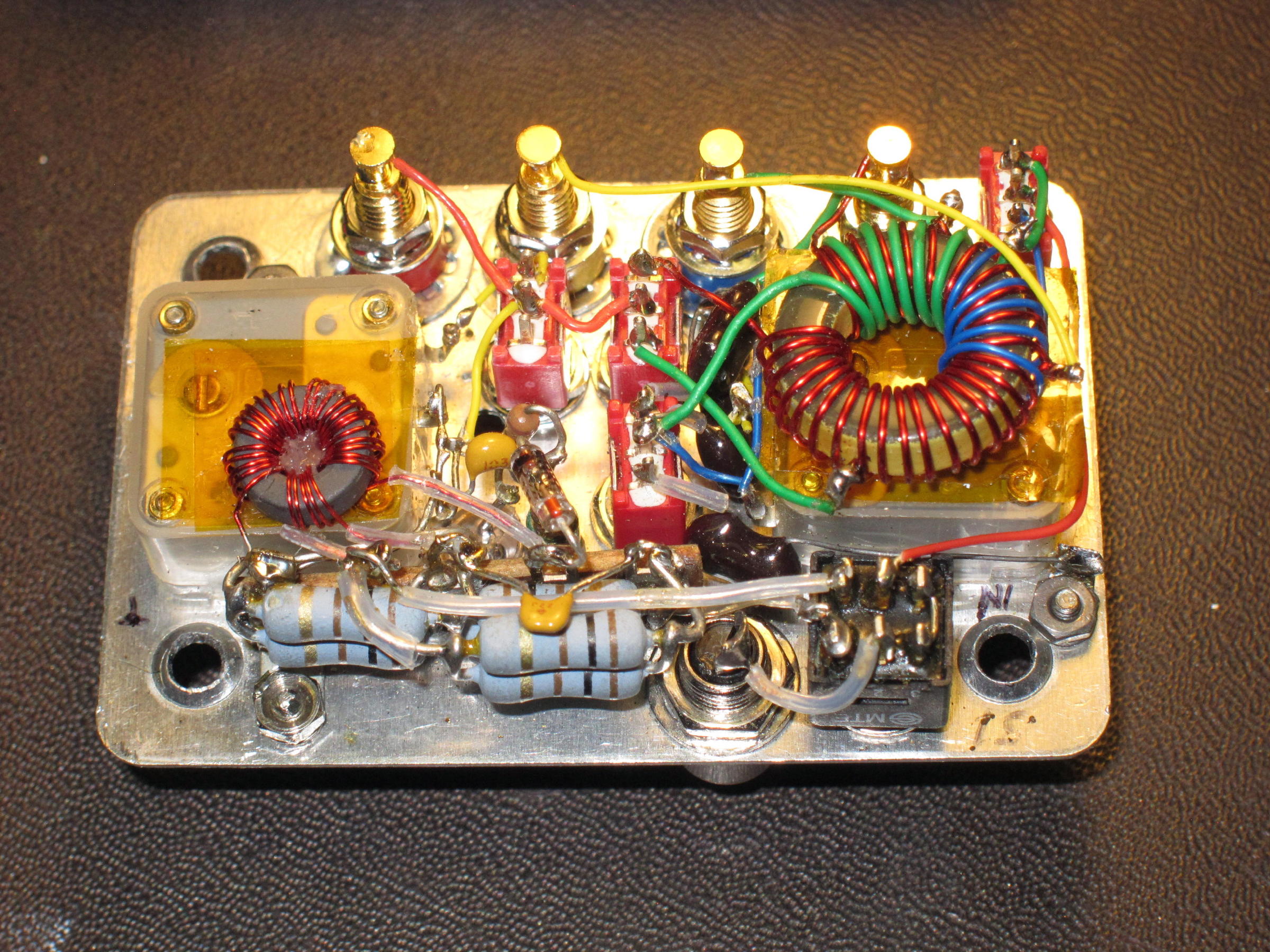
This tuner weighs less than 4 ounces (about 110 g).
The Tiny Tuner 2 preceded the larger tuner above; it was re-built from a different, earlier tuner - the “Tiny Tuner”. That tuner was derived partly from the BLT.
ORIGINAL CONCEPT DRAWING:
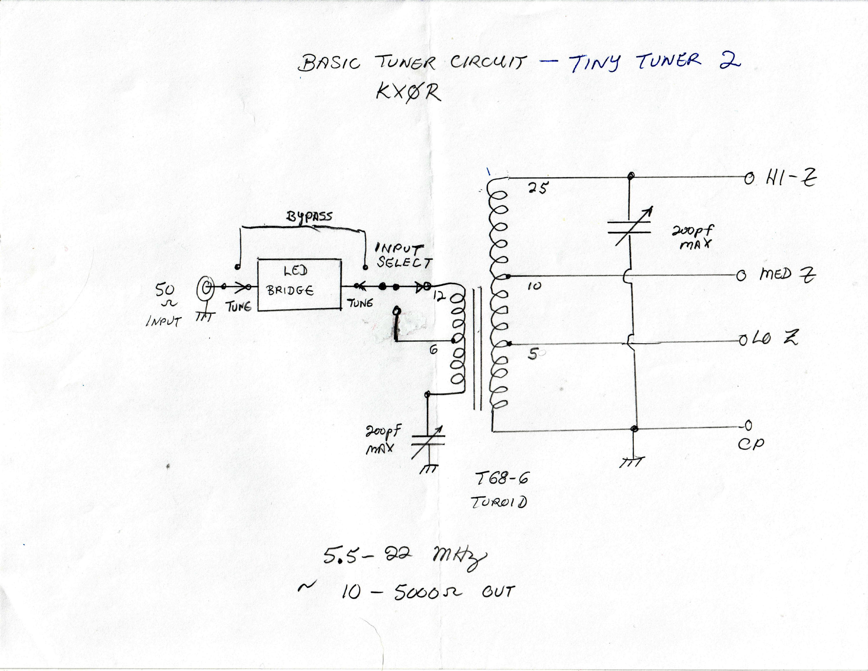
DETAILED DRAWING:

Concept, construction and components are similar to the larger version above. A T68-6 toroid is used, and the detailed drawing shows the turn counts. Note that the turns are different from those on the Concept drawing.
The secondary has 28 total turns, and the entire winding measures about 4.2 uH. The primary has 11 turns total, with a tap 5T from the top end. The primary is wound on the low-Z end of the secondary - see photo.
Operation is very similar to the larger tuner. 60M and 80M are not available, and the circuit is simpler and smaller. As far as I can tell, this tuner is just as good as the larger one, for the 5 bands it covers. It handles the 10W from the KX2 just fine!
Part of the intent of this article is to make SOTA activators aware that traditional RF rules are meant to be broken, to some degree. Antennas don’t need to be resonant, wires may be fed at the end, an actual physical counterpoise is not always needed, a ground is seldom required for SOTA, an effective antenna may be quite low, coax cable is not desirable for connecting to the antenna, and above all – compact, light equipment is better for SOTA!!
Hopefully some of you will enjoy building and using similar tuners as much as I do!
73
KX0R